Part E. Low Energy Link Layer Security
vAtlanta r00
This Part describes the Link Layer security for Bluetooth Low Energy.
1. Encryption and authentication overview
The Link Layer provides encryption and authentication using Counter with Cipher Block Chaining-Message Authentication Code (CCM) Mode, which shall be implemented consistent with the algorithm as defined in IETF RFC 3610 (http://www.ietf.org/rfc/rfc3610.txt) in conjunction with the AES-128 block cipher as defined in NIST Publication FIPS-197 (http://csrc.nist.gov/publications/fips/fips197/fips-197.pdf). A description of the CCM algorithm can also be found in the NIST Special Publication 800-38C (http://csrc.nist.gov/publications/PubsSPs.html).
This specification uses the same notation and terminology as the IETF RFC except for the block cipher key K that in this specification is called the session key (see Section 2.4) and for the Message Authentication Code (MAC) that in this specification is called the Message Integrity Check (MIC) to avoid confusion with the term Media Access Controller.
CCM has two size parameters, M and L. The Link Layer defines these to be:
M = 4; indicating that the MIC (authentication field) is 4 octets
L = 2; indicating that the Length field is 2 octets
CCM requires a new session key whenever encryption is started. CCM also requires a unique nonce value for each PDU that is protected by a given session key. The CCM nonce shall be 13 octets.
An ACL connection or a BIS (if present), may be either encrypted and authenticated or unencrypted and unauthenticated. A CIS shall be encrypted and authenticated if, and only if, the associated ACL connection is.
When encryption is enabled, all Data Physical Channel and Isochronous Physical Channel PDUs with a non-zero length Payload shall be encrypted and authenticated. Authentication is performed by appending a MIC field to the Payload. The MIC shall be calculated over the PDU’s Payload and the first octet of the header with certain bits (specified in Table 2.3) masked to zero. Encryption shall be applied to the PDU’s Payload and MIC.
Each new encrypted PDU with a non-zero length Payload shall be decrypted and authenticated before being sent to the Host or processed by the Link Layer. Authentication is unrelated to the Link Layer acknowledgment scheme; authentication does not have to be performed before the packet is acknowledged by the Link Layer.
In the event of an authentication failure being detected in a Data Physical Channel PDU or CIS Data PDU, the connection or stream carrying the affected PDU shall be considered lost (see [Vol 6] Part B, Section 4.5.12). The notification to the Host shall specify the error code Connection Terminated due to MIC Failure (0x3D). The peer Link Layer will detect this loss of connection through the supervision timeout procedure.
In the event of a MIC failure being detected in a Broadcast Isochronous PDU, synchronization shall be considered lost. The Link Layer shall not receive any further packets on the BIS and the Host shall be notified of the loss of synchronization with the error code Connection Terminated due to MIC Failure (0x3D).
1.1. Cryptographic Toolbox
The following cryptographic functions are defined:
h8 is used to generate group session keys for BIGs.
The building block for the cryptographic functions h8 is the security function AES‑CMAC.
When a multi-octet integer parameter is used as input to AES-CMAC inside the h8 function, the most significant octet of the integer shall be the first octet of the stream and the least significant octet of the integer shall be the last octet of the stream.
The functions h6 and h7 used in this Part are defined in [Vol 3] Part H, Section 2.2.
1.1.1. Group Session Key Derivation Function h8
The function h8 is used to generate the Group Session Key (GSK) for encrypting or decrypting payloads of an encrypted BIS. The definition of the h8 function makes use of the AES-CMAC function. The inputs to the function h8 are:
K is 128 bits S is 128 bits keyID is 32 bits
For the first AES-CMAC function, K is used as the data m and S is used as the key. The output of the first AES-CMAC function IK (intermediate key which is 128 bits) is used as the key for the second AES-CMAC function and keyID is used as the data m:
IK = AES-CMACS(K) h8(K, S, keyID) = AES-CMACIK(keyID)
1.1.2. Derivation of Group Session Key
The Link Layer shall derive the Group Long Term Key (GLTK) and Group Session Key (GSK) as follows:
IGLTK = h7(“BIG1”, Broadcast_Code) GLTK = h6(IGLTK, “BIG2”) GSK = h8 (GLTK, GSKD, “BIG3”)
The string "BIG1" is mapped into a SALT using ASCII as 0x00000000_00000000_00000000_42494731.
The string "BIG2" is mapped into a keyID using ASCII as 0x42494732.
The string "BIG3" is mapped into a keyID using ASCII as 0x42494733.
2. CCM
This section provides the details for using the CCM algorithm. As specified, the CCM algorithm requires the payload and some additional parameters to be formatted into the CCM nonce, counter-mode blocks and encryption blocks. The CCM nonce provides uniqueness to each packet. The counter-mode blocks are used to calculate the MIC. The encryption blocks provide the keystream that is used to encrypt the payload and the MIC of the Data Physical Channel PDU, CIS Data PDU, BIS Data PDU, and BIG Control PDU.
Sample data of the blocks (see Section 2.2 and Section 2.3) can be found in [Vol 6] Part C, Section 1 and Section 1.2.
2.1. CCM nonce
The CCM nonce is constructed from a 39-bit packetCounter, 1-bit directionBit and an 8-octet IV (initialization vector). The format of the 13-octet nonce shall be as shown in Table 2.1.
Octet | Field | Size (octets) | Value | Description |
|---|---|---|---|---|
0 | Nonce0 | 1 | variable | packetCounter[7:0] |
1 | Nonce1 | 1 | variable | packetCounter[15:8] |
2 | Nonce2 | 1 | variable | packetCounter[23:16] |
3 | Nonce3 | 1 | variable | packetCounter[31:24] |
4 | Nonce4 | 1 | variable | Bit 6 – Bit 0: packetCounter[38:32] Bit 7: directionBit |
5 | Nonce5 | 1 | variable | IV[7:0] |
6 | Nonce6 | 1 | variable | IV[15:8] |
7 | Nonce7 | 1 | variable | IV[23:16] |
8 | Nonce8 | 1 | variable | IV[31:24] |
9 | Nonce9 | 1 | variable | IV[39:32] |
10 | Nonce10 | 1 | variable | IV[47:40] |
11 | Nonce11 | 1 | variable | IV[55:48] |
12 | Nonce12 | 1 | variable | IV[63:56] |
The Link Layer shall maintain one packetCounter per Role for each ACL and CIS connection and one for each BIS that the Link Layer is transmitting or is synchronized to.
For each ACL connection, the packetCounter shall be set to zero for the first encrypted Data Physical Channel PDU sent during the encryption start procedure. The packetCounter shall then be incremented by one for each new Data Physical Channel PDU that is encrypted. The packetCounter shall not be incremented for retransmissions.
For each CIS, packetCounter shall equal cisPayloadCounter defined in [Vol 6] Part B, Section 4.5.13.1.
For each BIS, packetCounter shall equal bisPayloadCounter defined in [Vol 6] Part B, Section 4.4.6.3
The value of packetCounter used for a BIG Control PDU shall be equal to the value of packetCounter used in the first subevent of the BIG event that the BIG Control PDU is part of.
The directionBit shall be set to 1 for Data Physical Channel PDUs and CIS Data PDUs sent by the Central and set to 0 for Data Physical Channel PDUs and CIS Data PDUs sent by the Peripheral. The directionBit shall be set to 1 for Broadcast Isochronous PDUs sent by the Isochronous Broadcaster.
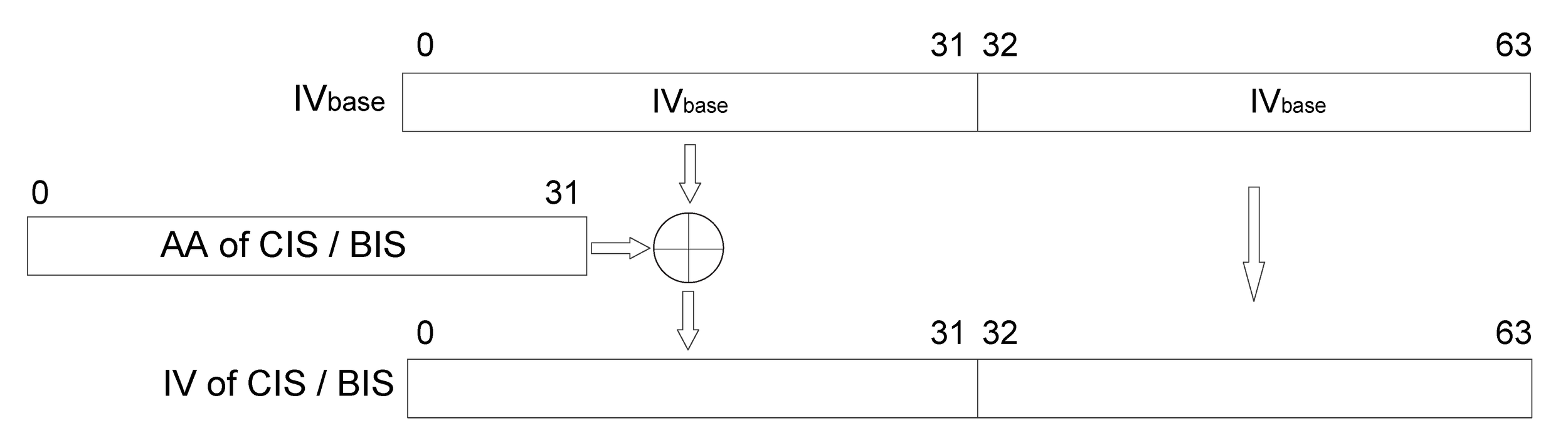
The IV is common for both Roles of an ACL and CIS. Whenever encryption is started or restarted, a new 8-octet IV shall be used for each pair of communicating devices. The IV for an ACL is determined as specified in [Vol 6] Part B, Section 5.1.3.1. The IV for a CIS or BIS is calculated from an IVbase and the Access Address of the CIS or BIS respectively. For a CIS, the IVbase shall be set to the value of IV of the associated ACL. For a BIS, the IVbase shall be set to the value of GIV contained in the BIGInfo. IV[31:0] shall equal IVbase[31:0] XORed with the Access Address of the CIS or BIS while IV [63:32] shall equal IVbase[63:32], as shown in Figure 2.1. The IV for a BIG control logical link shall be determined in the same way as for a BIS.
Note
Note: If a CIS is terminated or considered lost and then a new CIS with the same CIS_ID is created in the same CIG, the new CIS must still have a new access address (see [Vol 6] Part B, Section 2.1.2).
2.2. Counter mode blocks
For calculating the MIC, the multiple counter mode blocks are generated according to the CCM specification. These are referred to as blocks B0 – Bn. Table 2.2 defines the format of block B0. Table 2.3 defines the format of block B1 that is devoted to the authentication of the additional authenticated data. Additional B blocks are generated as needed for authentication of the payload.
Offset (octets) | Field | Size (octets) | Value | Description |
|---|---|---|---|---|
0 | Flags | 1 | 0x49 | As per the CCM specification |
1 | Nonce | 13 | variable | The nonce as described in Table 2.1. Nonce0 shall have offset 1. Nonce12 shall have offset 13. |
14 | Length[MSO] | 1 | 0x00 | The most significant octet of the length of the payload |
15 | Length[LSO] | 1 | variable | The least significant octet of the length of the payload |
Offset | Field | Size (octets) | Value | Description |
|---|---|---|---|---|
0 | AAD_Length[MSO] | 1 | 0x00 | The most significant octet of the length of the additional authenticated data |
1 | AAD_Length[LSO] | 1 | 0x01 | The least significant octet of the length of the additional authenticated data |
2 | AAD | 1 | variable | The PDU header’s first octet with the following bits masked to 0. Data Physical channel PDU: NESN, SN, MD. Connected Isochronous PDU: NESN, SN, NPI, CIE. Broadcast Isochronous PDU: CSSN, CSTF. |
3 | Padding | 13 | 0x00, 0x00, 0x00, 0x00, 0x00, 0x00, 0x00, 0x00, 0x00, 0x00, 0x00, 0x00, 0x00 | These octets are only used to pad the block. They are not part of the packet and never transmitted. |
2.3. Encryption blocks
The CCM algorithm uses the Ai blocks to generate keystream that is used to encrypt the MIC and the PDU payload. Block A0 is always used to encrypt and decrypt the MIC. Block A1 is always used to encrypt and decrypt the first 16 octets of the Payload. Subsequent blocks are always used to encrypt and decrypt the rest of the Payload as needed.
Offset (octets) | Field | Size (octets) | Value | Description |
|---|---|---|---|---|
0 | Flags | 1 | 0x01 | As per the CCM specification |
1 | Nonce | 13 | variable | The nonce as described above Nonce0 shall have offset 1. Nonce12 shall have offset 13. |
14 | i[MSO] | 1 | variable | The most significant octet of the counter i |
15 | i[LSO] | 1 | variable | The least significant octet of the counter i |
2.4. Session Keys
The session key for an ACL connection shall be generated as specified in [Vol 6] Part B, Section 5.1.3.1.
The session key for a CIS shall be the same as that for the associated ACL.
The session key for a BIS shall be the Group Session Key derived in Section 1.1.2.
3. Deterministic Random Bit Generator
The Link Layer provides the ability to generate random bit sequences using a Deterministic Random Bit Generator (DRBG), which is implemented consistent with the recommendations defined in NIST Special Publication 800-90Ar1 [1] with a security strength of 128 bits, in conjunction with the AES-128 block cipher. Table 3.1 shows the operational definitions for the DRBG specification.
Block Cipher | AES-128 |
|---|---|
Supported security strength | 128 bits |
Temporal key length | 128 bits |
Nonce vector V length | 128 bits |
Seed length | 256 bits |
Entropy input length | 128 bits |
Required minimum entropy for instantiation | 128 bits |
Personalization string length | 128 bits |
Maximum number of requests between reseeds | 248 |
The DRBG requires a temporal key KDRBG and a nonce vector VDRBG. These two values shall both be instantiated locally within each peer Controller before the first invocation of the DRBG within each LE connection on which CS is being used. The inputs to this instantiation procedure are the initialization vector, instantiation nonce, and personalization vector, which are the result of the CS Security Start procedure described in [Vol 6] Part B, Section 5.1.23. The nonce vector VDRBG shall be incremented at each invocation of the DRBG, and its value shall not repeat for the life of the DRBG temporal key. This increment function is described in Section 3.2.2.
The values of KDRBG and VDRBG shall not be exported outside the local Controller.
Figure 3.1 provides a functional overview of the DRBG function. Entropy material (a) in the form of an initialization vector, instantiation nonce, and personalization vector used to seed the DRBG, is generated from the CS Security Start procedure described in [Vol 6] Part B, Section 5.1.23. The instantiation function h9 (b) described in Section 3.1.5 is invoked to generate the security material for the DRBG. A CS step counter, transaction ID, and transaction counter are used to increment (c) the DRBG security nonce, as described in Section 3.2.2, which in turn is used as an input to the DRBG (d) to generate the required random bits (e) as described in Section 3.1.6. Finally, backtracking resistance (f) is invoked every time a new CS procedure is started, as described in Section 3.1.7.

3.1. Cryptographic toolbox
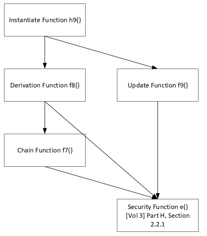
Section 3.1 defines several cryptographic functions for the DRBG. The instantiation function h9 and random bit generation function CS_DRBG are the primary cryptographic procedures, which in turn invoke subordinate functions. Figure 3.2 shows the call tree for the cryptographic toolbox described in this section.
 |
Within these cryptographic procedures, the following operations are used.
Operation | Meaning |
|---|---|
len( X ) | Computes the 8-bit byte length of X in octets |
leftmost( X ) | Returns the leftmost 128 bits of X |
rightmost( X ) | Returns the rightmost 128 bits of X |
3.1.1. Octet and bit ordering
With the exception of the random bit generation function CS_DRBG (see Section 3.1.6), all toolbox functions operate on one or more input arguments represented by a series of octets, and all toolbox functions output results that are a series of octets. With the exception of VDRBG, the leftmost to rightmost representation is indexed starting from octet 0, which is then followed by octet 1, and so on. For VDRBG, the leftmost to rightmost representation is indexed starting from octet 15 and ending with octet 0.
In several toolbox functions, the hexadecimal notation of the form 0xXXXXXX is used to represent a series of octet values necessary for the processing of that function. In these cases, the leftmost to rightmost representation is used. In the example below, 0x01 represents the leftmost octet and 0x06 represents the rightmost octet.
0x010203040506 |
In several toolbox functions, octet and bit strings may be converted to integers to perform a mathematical operation such as increment or modulus function. Let {b0, b1,… bn} represent that string in its leftmost to rightmost format. The following summation is then used to convert that bit string into an integer where i represents the position of each bit from the original bit string and is indexed from [0...n].
The reverse operation is used to convert an integer into a string of bits, using the same leftmost to rightmost format.
3.1.2. DRBG chain function f7
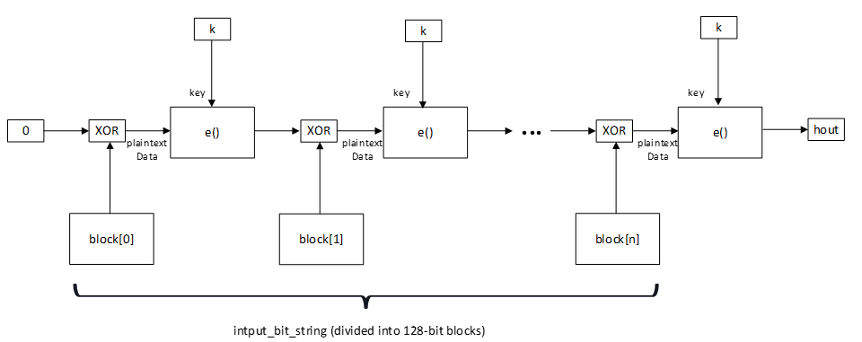
The DRBG chain function f7 takes a 128-bit key and an input string whose length is a multiple of 128 bits and generates an output that is 128 bits long using a cipher block chaining technique. The input string is segmented into 128-bit blocks that are processed in sequence. The security function e (see [Vol 3] Part H, Section 2.2.1) is invoked on each block whose output is XORed with the next block. This process is repeated until all input blocks are processed.
The following value is returned from f7:
hout is 128 bits
The following temporary values are used:
block[ i ] is an array of 128-bit string quantities
The input/output format of h7 is as follows:
hout = f7( k, input_bit_string )
f7 processing is as follows:
hout = 0x00000000000000000000000000000000 Starting with the leftmost bits of input_bit_string, split into 128-bit blocks from block[ 1 ] to block[ n ] for each block[ i ] hout = hout xor block[ i ] hout = e( k, hout ); return hout
The block diagram representing function f7() is shown in Figure 3.3.
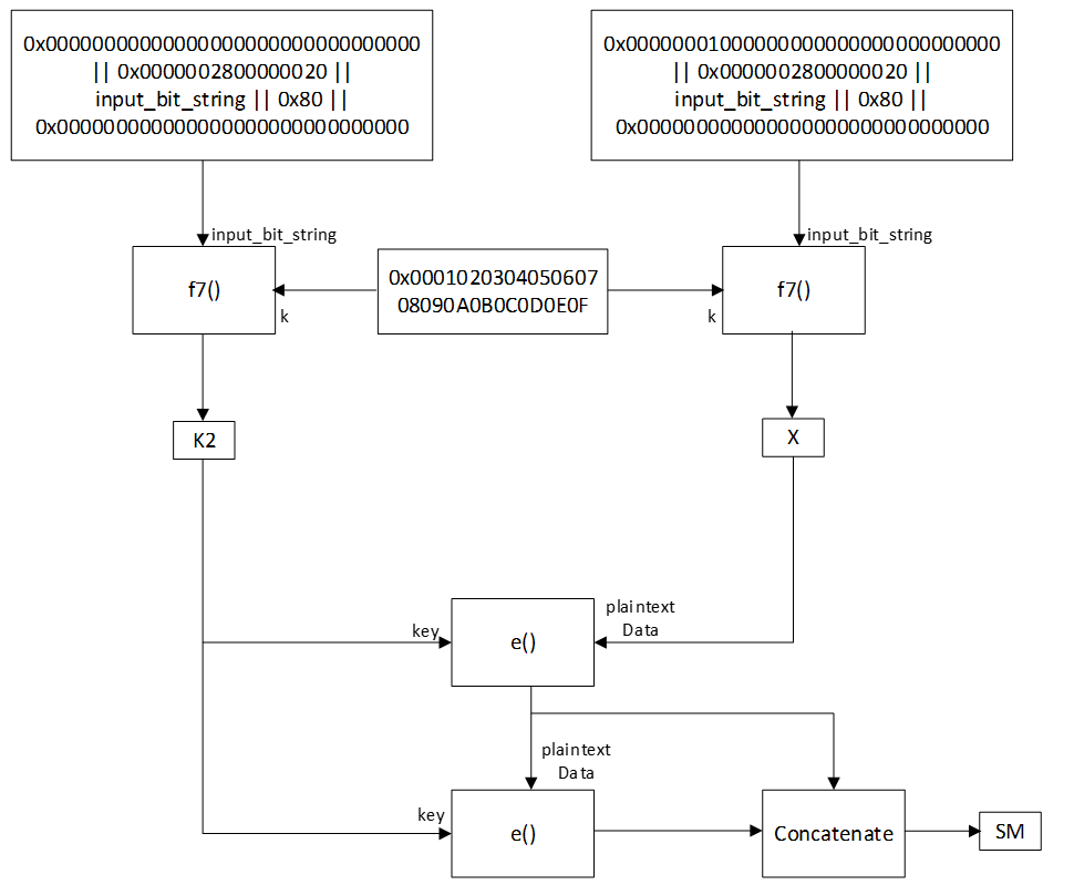
3.1.3. DRBG derivation function f8
The DRBG derivation function f8 is used to generate DRBG seed material that is 256 bits long. It takes an input bit string that is 320 bits long. Both f7 (see Section 3.1.2) and security function e (see [Vol 3] Part H, Section 2.2.1) are invoked by f8.
The following values are returned from f8:
SM is 256 bits
The following temporary values are used:
S is 512 bits K is 128 bits K2 is 128 bits V is 128 bits X is 128 bits
The input/output format of f8 is as follows:
SM = f8( input_bit_string )
The derivation function uses the input_bit_string to form a temporary bit string S constructed as shown below.
S = 0x0000002800000020 || input_bit_string || 0x80 || 0x000000000000000000000 000000000 K = 0x000102030405060708090A0B0C0D0E0F V = 0x00000000000000000000000000000000 K2 = f7( K, V || S ) V = 0x00000001000000000000000000000000 X = f7( K, V || S ) SM = e( K2, X ) SM = SM || e( K2, SM ) return SM
The block diagram representing function f8() is shown in Figure 3.4.
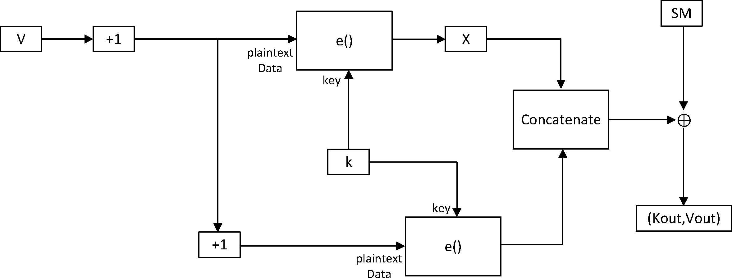
3.1.4. DRBG update function f9
The DRBG update function f9 is used to update and refresh a DRBG 128-bit temporal key K and a 128-bit nonce vector V using a 256-bit seed material (SM) that may carry fresh entropy. The SM value may also be 0 if f9 is called for backtracking purposes, as described in Section 3.1.7. The security function e (see [Vol 3] Part H, Section 2.2.1) is invoked by f9.
The following values are returned from f9:
Kout is 128 bits Vout is 128 bits
The following temporary values are used:
X is 256 bits
The input/output format of f9 is as follows:
Kout, Vout = f9( SM, K, V )
f9 processing is as follows:
V = V[127:8] || (( V[7:0] + 1 ) mod 28) X = e( K, V ) V = V[127:8] || (( V[7:0] + 1 ) mod 28) X = X || e( K, V ) X = X SM Kout = leftmost( X ) Vout = rightmost( X ) return Kout, Vout
The block diagram representing function f9() is shown in Figure 3.5.
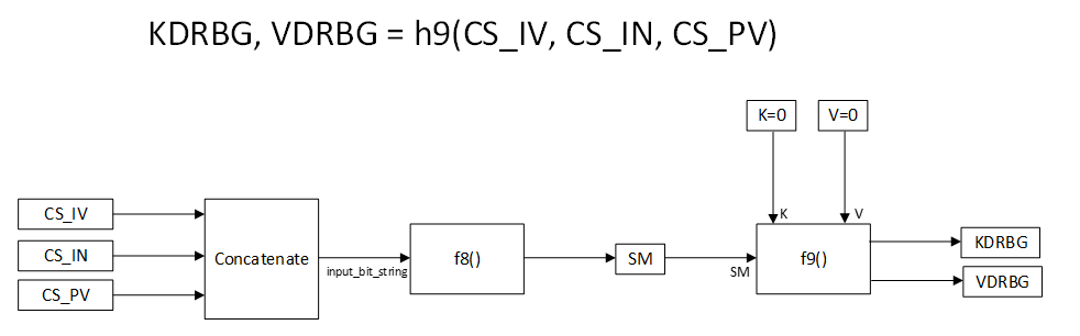
3.1.5. DRBG instantiation function h9
The DRBG instantiation function h9 is used to instantiate the DRBG temporal key KDRBG and a nonce vector VDRBG. The inputs to h9 are the 128-bit CS_IV, 64-bit CS_IN, and 128-bit CS_PV values that are the result of the CS Security Start procedure described in [Vol 6] Part B, Section 5.1.23. SM below represents the derived seed material for the DRBG instantiation.
The following values are returned from h9:
KDRBG is 128 bits VDRBG is 128 bits
The following temporary values are used:
SM is 256 bits K is 128 bits V is 128 bits
The input/output format of h9 is as follows:
KDRBG, VDRBG = h9( CS_IV, CS_IN, CS_PV )
In the instantiation function, both a seed derivation function f8 (see Section 3.1.3) and a key and nonce vector update function f9 (see Section 3.1.4) are invoked.
SM = f8( CS_IV || CS_IN || CS_PV ) K = 0x00000000000000000000000000000000 V = 0x00000000000000000000000000000000 KDRBG, VDRBG = f9( SM, K, V ) return KDRBG, VDRBG
The block diagram representing function h9() is shown in Figure 3.6.
3.1.6. Random bit generation function CS_DRBG
Random bit generation function CS_DRBG makes use of the security function e (see [Vol 3] Part H, Section 2.2.1) to generate a fresh 128-bit random bit sequence. The instantiated key and nonce vector V values are described in Section 3.
randomBits[0:127] = e( KDRBG, VDRBG + counters ) CS_DRBG( number of required bits ) ⊆ randomBits[0:127]
Refer to Section 3.2.1 for a description of the counters that contribute the nonce V value.
The maximum number of bits that may be generated in any single invocation is 128 bits. The number of required bits may vary from operation to operation. If less than 128 bits are required, then the return value of CS_DRBG shall be a subset of the bits returned from security function e The subset of bits shall be extracted starting from the most significant bit in leftmost to rightmost order. For example, on a new invocation of e, if an operation requires 8-bit values, then randomBits[0:7] would be the first set used, randomBits[8:15] would be the second set used, and so on. If at any point the number of required bits exceeds the number of fresh bits remaining to draw upon, then the remaining bits shall be discarded, the nonce vector VDRBG shall be updated (see Section 3.2.2), and the security function e shall be invoked again.
Depending on the operation, the random bits may also be used as unsigned integer values. If unsigned integer values are used, the most significant bit returned shall represent the most significant bit of the unsigned integer that is formed from that set of bits.
3.1.7. DRBG backtracking resistance
Backtracking resistance as described in [1] is included in DRBG. Backtracking resistance shall be invoked every time the CSProcCount is incremented (see [Vol 6] Part B, Section 5.1.26) before the first invocation of the CS_DRBG for that CS procedure (see Section 3.1.6).
The procedure for backtracking resistance makes use of the DRBG update function f9 (see Section 3.1.4) to update the KDRBG and VDRBG values for any subsequent CS procedure. The inputs to f9 are the running set of values for KDRBG and VDRBG. From this value, the CS Transaction_Identifier field shall be set as described in [Vol 6] Part H, Section 4.8. The CS Step_Counter and CS Transaction_Counter fields shall be reset to zero relative to this VDRBG value. The procedure for applying these modifications of the VDRBG value is described in Section 3.2.2.
The following values are returned from f9 when used for backtracking resistance:
KDRBG is 128 bits VDRBG is 128 bits
f9 is invoked as follows using the values for KDRBG and VDRBG as described above as inputs:
KDRBG, VDRBG = f9( 0, KDRBG, VDRBG ) return KDRBG, VDRBG
3.2. DRBG based on a block cipher
The Deterministic Random Bit Generator uses a block cipher as described in [1]. The block cipher employed is the security function e described in [Vol 3] Part H, Section 2.2.1. The inputs to e for the DRBG are key KDRBG and nonce vector VDRBG, both of which shall be instantiated using security function h9 as described in Section 3.1.5, and afterwards updated using security function f9 as described in Section 3.1.4, before any use of the DRBG.
3.2.1. DRBG nonce V
The instantiation content of the nonce V vector, as described in Section 3.1.5 represents the starting value from which the DRBG increment function operates. From that starting value, several nonce counter fields are defined, as shown in Table 3.3. Each counter field octet is structured in leftmost to rightmost bit format, from bit 7 to bit 0.
Octet | Field | Size (octets) | Value | Description |
|---|---|---|---|---|
0 | Counter0 | 1 | variable | 8-bit CS Transaction_Counter, with bit 7 being the most significant bit |
1 | Counter1 | 1 | variable | 8-bit CS Transaction_Identifier, with bit 7 being the most significant bit |
2 | Counter2 | 1 | variable | Octet 0 (LSO) of the CS Step_Counter, with bit 7 being the most significant bit |
3 | Counter3 | 1 | variable | Octet 1 (MSO) of the CS Step_Counter, with bit 7 being the most significant bit |
4 | Counter4 | 1 | fixed | Bits remain set as instantiated or updated for the life of the DRBG key |
5 | Counter5 | 1 | fixed | Bits remain set as instantiated or updated for the life of the DRBG key |
6 | Counter6 | 1 | fixed | Bits remain set as instantiated or updated for the life of the DRBG key |
7 | Counter7 | 1 | fixed | Bits remain set as instantiated or updated for the life of the DRBG key |
8 | Counter8 | 1 | fixed | Bits remain set as instantiated or updated for the life of the DRBG key |
9 | Counter9 | 1 | fixed | Bits remain set as instantiated or updated for the life of the DRBG key |
10 | Counter10 | 1 | fixed | Bits remain set as instantiated or updated for the life of the DRBG key |
11 | Counter11 | 1 | fixed | Bits remain set as instantiated or updated for the life of the DRBG key |
12 | Counter12 | 1 | fixed | Bits remain set as instantiated or updated for the life of the DRBG key |
13 | Counter13 | 1 | fixed | Bits remain set as instantiated or updated for the life of the DRBG key |
14 | Counter14 | 1 | fixed | Bits remain set as instantiated or updated for the life of the DRBG key |
15 | Counter15 | 1 | fixed | Bits remain set as instantiated or updated for the life of the DRBG key |
3.2.2. DRBG nonce increment function
The Link Layer shall maintain one DRBG nonce/counter (V) value per ACL connection as described in Section 3.2.1.
The management of the nonce V CS Step_Counter field, CS Transaction_Identifier field, and CS Transaction_Counter field are described in this section. All other fields in the nonce V counter shall be set relative to the VDRBG content resulting from either the procedure described in Section 3.1.5 or the Backtracking Resistance procedure described in Section 3.1.7.
The nonce V CS Step_Counter field shall be initialized from the VDRBG value resulting from either the instantiation procedure described in Section 3.1.5 or the Backtracking Resistance procedure described in Section 3.1.7. This value shall be used for invocations of the DRBG that are necessary to the start of the first step of a CS procedure. Thereafter, the nonce V CS Step_Counter initialization value shall be added to the step number, CSStepCount at the time that the DRBG is invoked again, as described in [Vol 6] Part H, Section 4.3, modulo 216.
CS Step_Counter = (VDRBG[31:16] + CSStepCount) mod 216
The CS Step_Counter value shall not exceed a value of 216 - 1 when used within the CS Step_Counterfield of the nonce V value in each CS procedure instance. The DRBG is not invoked at every CS step within a CS procedure.
The nonce V CS Transaction_Identifier field shall be set to a specific transaction identifier, CSTransactionID as defined in [Vol 6] Part H, Section 4.8, added to the VDRBG value resulting from either the instantiation procedure (see Section 3.1.5) or the Backtracking Resistance procedure (see Section 3.1.7), modulo 28.
CS Transaction_Identifier = (VDRBG[15:8] + CSTransactionID) mod 28
The nonce V CS Transaction_Counter field is incremented in conjunction with each CS transaction identifier type defined in [Vol 6] Part H, Section 4.8. That is, for each CS transaction identifier type, it might be necessary to invoke the DRBG one or more times. The CS Transaction_Counter field shall be incremented each time the DRBG is invoked for that specific CS transaction identifier type at a specific CS step. A separate CS Transaction_Counter field value shall be maintained for each possible CS transaction identifier type because the invocation of the DRBG might be interleaved with different CS transaction identifier types at any one CS step. In the next two paragraphs, the possible CS Transaction_Counter field values are referred to collectively as the CS Transaction_Counter field.
The CS Transaction_Counter field shall be initialized to the VDRBG value resulting from either the instantiation procedure (see Section 3.1.5) or the Backtracking Resistance procedure (see Section 3.1.7), each time the nonce V CS Step_Counter field is set to a new value. The CS Transaction_Counter initialization value shall be added to the transaction counter, CSTransactionCounter as defined in [Vol 6] Part H, Section 4.8 before each invocation of the DRBG, for the specific CS Transaction_Identifier field setting.
CS Transaction_Counter = (VDRBG[7:0] + CSTransactionCounter) mod 28
The CS Transaction_Counter field shall not be incremented more than 28 – 1 times for any combined single setting for the CS Transaction_Identifier and the CS Step_Counter fields.
4. References
[1] NIST Special Publication 800-90A Rev. 1, "Recommendation for Random Number Generation Using Deterministic Random Bit Generators", https://csrc.nist.gov/publications/detail/sp/800-90a/rev-1/final