Part H. Security Specification
vAtlanta r00
This Part describes the security system which may be used at the Link Layer. The Encryption, Authentication, and Key Generation schemes are specified. The requirements for the supporting process of random number generation are also specified.
1. Security overview
Bluetooth wireless technology provides peer-to-peer communications over short distances. In order to provide usage protection and information confidentiality, the system provides security measures both at the application layer and the Link Layer. These measures are designed to be appropriate for a peer environment.
This means that in each device, the authentication and encryption routines are implemented in the same way.
In [Vol 2] Part H, the term "random number" includes pseudo-random numbers, subject to the requirements in Section 2.
The security mechanisms used in BR/EDR have evolved over the course of multiple versions of the specification in three phases: legacy, Secure Simple Pairing, and Secure Connections. The encryption, authentication and key generation algorithms associated with each is shown in Table 1.1.
Security Mechanism | Legacy | Secure Simple Pairing | Secure Connections |
|---|---|---|---|
Encryption | E0 | E0 | AES-CCM |
Authentication | SAFER+ | SAFER+ | HMAC-SHA256 |
Key Generation | SAFER+ | P-192 ECDH HMAC-SHA-256 | P-256 ECDH HMAC-SHA-256 |
The legacy encryption, authentication and key generation algorithms are described in Section 3 to 6. The algorithms used for Secure Simple Pairing and Secure Connections are described in Section 7 to 9.
Four different entities are used for maintaining security at the Link Layer: a Bluetooth Device Address, two secret keys, and a random number that shall be regenerated for each new transaction. The four entities and their sizes are summarized in Table 1.2.
Entity | Size |
|---|---|
BD_ADDR | 48 bits |
Private user key, authentication | 128 bits |
Private user key, encryption configurable length (byte-wise) | 8 to 128 bits |
RAND | 128 bits |
The Bluetooth Device Address (BD_ADDR) is the 48-bit address. The BD_ADDR can be obtained via user interactions, or, automatically, via an inquiry routine by a device.
The secret keys are derived during initialization and are never disclosed. The encryption key is derived from the authentication key during the authentication process. For the authentication algorithm, the size of the key used is always 128 bits. For the encryption algorithm, the key size may vary between 1 and 16 octets (8 - 128 bits).
The encryption key is entirely different from the authentication key. Each time encryption is activated, a new encryption key shall be generated. Thus, the lifetime of the encryption key does not necessarily correspond to the lifetime of the authentication key.
It is anticipated that the authentication key will be more static in its nature than the encryption key – once established, the particular application running on the device decides when, or if, to change it. To underline the fundamental importance of the authentication key to a specific link, it is often referred to as the link key.
RAND is a random number which can be derived from a random process in the device. This is not a static parameter and will change frequently.
In this part, the terms user and application are used interchangeably to designate the entity that is at either side.
1.1. Pausing encryption and role switch
To perform a role switch on a connection encryption must be disabled or paused as the encryption is based off the Central's clock and Bluetooth address information. Unfortunately, if the role switch is required, and encryption is turned off, the device on the other end of the link will not be aware of the reason for disabling encryption, and can therefore take two possible actions: send clear text data, or disconnect. Neither of these possible actions is desirable. When performing a role switch on an encrypted link, the role switch shall be performed as a single operation where possible. If this is not possible because the other device does not support the encryption pause feature, then when a device wishes to have an encrypted link, and encryption is disabled, then the device should not send any user data, and should not disconnect. If both devices support the encryption pause feature, then this procedure shall be used.
1.2. Change connection link keys
It is possible to perform a change of connection link keys while a link is encrypted, but it is not possible to use the new link keys until encryption has been stopped and then restarted. As with role switches, disabling encryption and then re-enabling it again can cause user data to be sent in the clear or a disconnection to occur. The use of encryption pausing prevents this problem from occurring. On devices that do not support the encryption pause feature, when a device wishes to have an encrypted link, and encryption is disabled, then the device should not send any data, and should not disconnect. If both devices support the encryption pause feature, then this procedure shall be used.
1.3. Periodically refreshing encryption keys
If both devices support the encryption pause feature, then the encryption keys shall be refreshed by the Link Manager at least once every 228 ticks of the Bluetooth clock (about 23.3 hours) when E0 encryption is used and before either the PayloadCounter or dayCounter roll over when AES-CCM encryption is used if it is not refreshed by the Host or the remote Link Manager. To refresh an encryption key, the Host may use the Change Connection Link Key procedure or request an encryption key refresh. If the encryption key has not been refreshed before going stale, a device may disconnect the link.
Note
Note: The roll over will occur after at least 238 ticks of the Bluetooth clock or at least 2.72 years.
2. Random number generation
Each device shall have a random number generator. Random numbers are used for many purposes within the security functions – or instance, for the challenge-response scheme, for generating authentication and encryption keys, nonces used in Secure Simple Pairing, for Passkeys used in authentication. A device shall use a random number generator compliant with [FIPS PUB 140-2] (http://csrc.nist.gov/publications/fips/fips140-2/fips1402annexc.pdf) or a later update.
When using a pseudo-random number generator, the device shall use a seed with at least the minimum entropy required by that pseudo-random number generator.
The random number generator shall be tested against the [FIPS SP800-22] (http://csrc.nist.gov/publications/nistpubs/800-22-rev1a/SP800-22rev1a.pdf). This encompasses the verification of the following statistical tests performed on the output of the PRNG as specified by the [FIPS SP800-22]:
The Frequency (Monobit) Test
Frequency Test within a Block
The Runs Test
Test for the Longest-Run-of-Ones in a Block
The Binary Matrix Rank Test
The Discrete Fourier Transform (Spectral) Test
The Non-overlapping Template Matching Test
The Overlapping Template Matching Test
Maurer's "Universal Statistical" Test
The Linear Complexity Test
The Serial Test
The Approximate Entropy Test
The Cumulative Sums (Cusums) Test
The Random Excursions Test
The Random Excursions Variant Test
These tests are part of standard statistical mathematical packages. Some test suites, like the Diehard test suite, can be used to verify FIPS compliance. Alternatively, other tools, such as the DieHarder (http://www.phy.duke.edu/~rgb/General/rand_rate.php) or the available NIST tools (http://csrc.nist.gov/groups/ST/toolkit/random_number.html) and the corresponding recommendations (http://csrc.nist.gov/publications/nistpubs/800-22-rev1/SP800-22rev1.pdf) may also be used.
3. Key management
It is important that the encryption key size within a specific device cannot be set by the user – this should be a factory preset entity. In order to prevent the user from over-riding the permitted key size, the Bluetooth Baseband processing shall not accept an encryption key given from higher software layers. Whenever a new encryption key is required, it shall be created as defined in Section 6.4.
Changing a link key shall also be done through the defined Baseband procedures. Depending on what kind of link key it is, different approaches are required. The details are found in Section 3.2.7.
3.1. Key types
The link key is a 128-bit random number which is shared between two or more parties and is the base for all security transactions between these parties. The link key itself is used in the authentication routine. Moreover, the link key is used as one of the parameters when the encryption key is derived.
In the following, a session is defined as the time interval for which the device is a member of a particular piconet. Thus, the session terminates when the device disconnects from the piconet.
The link keys are either semi-permanent or temporary. A semi-permanent link key may be stored in non-volatile memory and may be used after the current session is terminated. Consequently, once a semi-permanent link key is defined, it may be used in the authentication of several subsequent connections between the devices sharing it. The designation semi-permanent is justified by the possibility of changing it. How to do this is described in Section 3.2.7.
The lifetime of a temporary link key is limited by the lifetime of the current session – it shall not be reused in a later session. Typically, in a point-to-multipoint configuration where the same information is to be distributed securely to several recipients, a common encryption key is useful. To achieve this, the temporary link key replaces the semi-permanent link keys. The details of this procedure are found in Section 3.2.6.
In the following, the current link key is the link key in use at the current moment. It can be semi-permanent or temporary. Thus, the current link key is used for all authentications and all generation of encryption keys in the on-going connection (session).
In order to accommodate different types of applications, three types of link keys have been defined:
the combination key KAB
the temporary key K_temp
the initialization key Kinit
In addition to these keys there is an encryption key, denoted K_enc. This key is derived from the current link key. Whenever encryption is activated by an LM command, the encryption key shall be changed automatically. The purpose of separating the authentication key and encryption key is to facilitate the use of a shorter encryption key without weakening the strength of the authentication procedure. There are no governmental restrictions on the strength of authentication algorithms. However, in some countries, such restrictions exist on the strength of encryption algorithms.
The combination key is derived from information in both devices A and B, and is therefore always dependent on two devices. The combination key is derived for each new combination of two devices.
The temporary link key, K_temp, shall only be used during the current session. It shall only replace the original link key temporarily. For example, this may be utilized when a Central wants to reach more than one device simultaneously using the same encryption key, see Section 3.2.6.
The initialization key, Kinit, shall be used as the link key during the initialization process when no combination keys have been defined and exchanged yet or when a link key has been lost. The initialization key protects the transfer of initialization parameters. The key is derived from a random number, an L-octet PIN code, and a BD_ADDR. This key shall only be used during initialization.
The PIN may be a fixed number provided with the device (for example when there is no user interface). Alternatively, the PIN can be selected by the user, and then entered in both devices that are to be matched. The latter procedure should be used when both devices have a user interface, for example a phone and a laptop. Entering a PIN in both devices is more secure than using a fixed PIN in one of the devices, and should be used whenever possible. Even if a fixed PIN is used, it shall be possible to change the PIN; this is in order to prevent re-initialization by users who once obtained the PIN. If no PIN is available, a default value of zero may be used. The length of this default PIN is one byte, PIN (default) = 0x00. This default PIN may be provided by the Host.
For many applications the PIN code will be a relatively short string of numbers. Typically, it may consist of only four decimal digits. Even though this gives sufficient security in many cases, there exist countless other, more sensitive, situations where this is not reliable enough. Therefore, the PIN code may be chosen to be any length from 1 to 16 octets. For the longer lengths, the devices exchanging PIN codes may use software at the application layer rather than mechanical (i.e. human) interaction. For example, this can be a Diffie-Hellman key agreement, where the exchanged key is passed on to the generation process in both devices, just as in the case of a shorter PIN code.
3.2. Key generation and initialization
The link keys must be generated and distributed among the devices in order to be used in the authentication procedure. Since the link keys shall be secret, they shall not be obtainable through an inquiry routine in the same way as the Bluetooth Device Addresses. The exchange of the keys takes place during an initialization phase which shall be carried out separately for each two devices that are using authentication and encryption. The initialization procedures consist of the following five parts:
generation of an initialization key
generation of link key
link key exchange
authentication
generation of encryption key in each device (optional)
After the initialization procedure, the devices can proceed to communicate, or the link can be disconnected. If encryption is implemented, the algorithm shall be used with the proper encryption key derived from the current link key. For any new connection established between devices A and B, they shall use the common link key for authentication, instead of once more deriving from the PIN. A new encryption key derived from that particular link key shall be created next time encryption is activated.
If no link key is available, the LM shall automatically start an initialization procedure.
3.2.1. Generation of initialization key, Kinit
A link key is used temporarily during initialization, the initialization key . This key shall be derived by the algorithm from a BD_ADDR, a PIN code, the length of the PIN (in octets), and a random number IN_RAND. The principle is depicted in Figure 6.4. The 128-bit output from shall be used for key exchange during the generation of a link key. When the devices have performed the link key exchange, the initialization key shall be discarded.
When the initialization key is generated, the PIN is augmented with the BD_ADDR. If one device has a fixed PIN the BD_ADDR of the other device shall be used. If both devices have a variable PIN the BD_ADDR of the device that received IN_RAND shall be used. If both devices have a fixed PIN they cannot be paired. Since the maximum length of the PIN used in the algorithm cannot exceed 16 octets, it is possible that not all octets of BD_ADDR will be used. This procedure ensures that depends on the identity of the device with a variable PIN. A fraudulent device may try to test a large number of PINs by claiming another BD_ADDR each time. It is the application’s responsibility to take countermeasures against this threat. If the device address is kept fixed, the waiting interval before the next try may be increased exponentially (see Section 5.1).
The details of the algorithm can be found in Section 6.3.
3.2.2. Authentication
The legacy authentication procedure shall be carried out as described in Section 5. During each legacy authentication, a new AU_RAND_A shall be issued.
For legacy authentication, mutual authentication is achieved by first performing the authentication procedure in one direction and then immediately performing the authentication procedure in the opposite direction.
The secure authentication procedure is always a mutual authentication. Secure authentication shall be carried out as described in Section 7.7.8. During each secure authentication, new AU_RAND_C and AU_RAND_P shall be used.
As a side effect of a successful authentication procedure an auxiliary parameter, the Authenticated Ciphering Offset (ACO), will be computed. The ACO shall be used for ciphering key generation as described in Section 3.2.5.
The claimant/verifier status is determined by the LM.
3.2.3. [This section is no longer used]
3.2.4. Generation of a combination key
To use a combination key, it is first generated during the initialization procedure. The combination key is the combination of two numbers generated in device A and B, respectively. First, each device shall generate a random number, LK_RANDA and LK_RANDB. Then, utilizing with the random number and their own BD_ADDRs, the two random numbers
and
shall be created in device A and device B, respectively. These numbers constitute the devices’ contribution to the combination key that is to be created. Then, the two random numbers LK_RANDA and LK_RANDB shall be exchanged securely by XORing with the current link key, . Thus, device A shall send to device B, while device B shall send to device A. If this is done during the initialization phase the link key . If CA is identical to CB, then the devices shall terminate the process of generating the combination key (e.g., by rejecting the following authentication).
When the random numbers and have been mutually exchanged, each device shall recalculate the other device’s contribution to the combination key. This is possible since each device knows the Bluetooth Device Address of the other device. Thus, device A shall calculate (EQ 2) and device B shall calculate (EQ 1). After this, both devices shall XOR the two numbers to generate the 128-bit link key. The result shall be stored in device A as the link key and in device B as the link key . If the resulting link key consists of all zeroes, then the devices shall discard the link key and terminate the process of generating the combination key (see [Vol 2] Part C, Section 4.2.1). When both devices have derived the new combination key, a mutual authentication procedure shall be initiated to confirm the success of the transaction. The old link key shall be discarded after a successful exchange of a new combination key. The message flow between Central and Peripheral and the principle for creating the combination key is depicted in Figure 3.1.

3.2.5. Generating the encryption key
The encryption key, K_enc, is derived by algorithm from the current link key, a 96-bit Ciphering OFfset number (COF), and a 128-bit random number. The COF is determined in one of two ways. If the current link key is a temporary link key, then COF shall be derived from the Central’s BD_ADDR. Otherwise the value of COF shall be set to the value of ACO as computed during the authentication procedure. Therefore:
There is an explicit call of when the LM activates encryption. Consequently, the encryption key is automatically changed each time the device enters encryption mode. The details of the key generating function can be found in Section 6.4.
3.2.6. Point-to-multipoint configuration
It is possible for the Central to use separate encryption keys for each Peripheral in a point-to-multipoint configuration with ciphering activated. Then, if the application requires more than one Peripheral to listen to the same payload, each Peripheral must be addressed individually. This can cause unwanted capacity loss for the piconet. Moreover, a Peripheral might not be capable of switching between two or more encryption keys in real time (e.g., after looking at the LT_ADDR in the header). Thus, the Central cannot use different encryption keys for broadcast messages and individually addressed traffic. Therefore, the Central may tell several Peripherals to use a common link key (and, hence, indirectly also to use a common encryption key) and may then broadcast the information encrypted. For many applications, this key is only of temporary interest. In the following discussion, this key is denoted by K_temp.
The transfer of necessary parameters shall be protected by the routine described in Section 3.2.8. After the confirmation of successful reception in each Peripheral, the Central shall issue a command to the Peripherals to replace their respective current link key by the new temporary link key. Before encryption can be activated, the Central shall also generate and distribute a common EN_RAND to all participating Peripherals. Using this random number and the newly derived temporary link key, each Peripheral shall generate a new encryption key.
The Central negotiates the encryption key length to use individually with each Peripheral that will use the temporary link key. If the Central has already negotiated with some of these Peripherals, it has knowledge of the sizes that can be accepted. There may be situations where the permitted key lengths of some devices are incompatible. In that case, the Central shall exclude the limiting device from the group.
When all Peripherals have received the necessary data, the Central can communicate information on the piconet securely using the encryption key derived from the new temporary link key. Each Peripheral in possession of the temporary link key can eavesdrop on all encrypted traffic, not only the traffic intended for itself. The Central may tell all participants to fall back to their old link keys simultaneously.
3.2.7. Modifying the link keys
If the key change concerns combination keys, then the procedure is straightforward. The change procedure is identical to the procedure described in Figure 3.1, using the current value of the combination key as link key. This procedure can be carried out at any time after the authentication and encryption start. Since the combination key corresponds to a single link, it can be modified each time this link is established. This will improve the security of the system since then old keys lose their validity after each session.
Starting up an entirely new initialization procedure is also possible. In that case, user interaction is necessary since a PIN will be required in the authentication and encryption procedures.
3.2.8. Generating a temporary link key
The key-change routines described so far are semi-permanent. To create the temporary link key, which can replace the current link key during a session (see Section 3.2.6), other means are needed. First, the Central shall create a new link key from two 128-bit random numbers, RAND1 and RAND2. This shall be done by
This key is a 128-bit random number. The reason for using the output of and not directly choosing a random number as the key, is to avoid possible problems with degraded randomness due to a poor implementation of the random number generator within the device.
Then, a third random number, RAND, shall be transmitted to the Peripheral. Using with the current link key and RAND as inputs, both the Central and the Peripheral shall compute a 128-bit overlay. The Central shall send the bitwise XOR of the overlay and the new link key to the Peripheral. The Peripheral, who knows the overlay, shall recalculate K_temp. To confirm the success of this transaction, the devices shall perform a mutual authentication procedure using the new link key. This procedure shall then be repeated for each Peripheral that receives the new link key. The ACO values from the authentications shall not replace the current ACO, as this ACO is needed to (re)compute a ciphering key when the Central falls back to the previous (semi-permanent) link key.
The Central activates encryption by an LM command. Before activating encryption, the Central shall ensure that all Peripherals receive the same random number, EN_RAND, since the encryption key is derived through the means of individually in all participating devices. Each Peripheral shall compute a new encryption key as follows:
where the value of COF shall be derived from the Central’s BD_ADDR as specified by equation (EQ 3). The details of the encryption key generating function are described in Section 6.4. The message flow between the Central and the Peripheral when generating the temporary link key is depicted in Figure 3.2.
Note
Note: In this case the ACO produced during the authentication is not used when computing the ciphering key.

4. Encryption (E0)
User information can be protected by encryption of the packet payload; the access code and the packet header shall never be encrypted. The encryption of the payload shall be carried out with a stream cipher called E0 that shall be re-synchronized for every payload. The overall principle is shown in Figure 4.1.
The stream cipher system E0 shall consist of three parts:
the first part performs initialization (generation of the session key). The session key generator shall combine the input bits in an appropriate order and shall shift them into the four LFSRs used in the key stream generator.
the second part generates the key stream bits and shall use a method derived from the summation stream cipher generator attributable to Massey and Rueppel. The second part is the main part of the cipher system, as it will also be used for initialization.
the third part performs encryption and decryption.

4.1. Encryption key size negotiation
Each device implementing the Baseband specification shall have a parameter defining the maximal allowed key length, L_max, 1 ≤ L_max ≤ 16 (number of octets in the key). For each application using encryption, a number L_min shall be defined indicating the shortest acceptable key size for that particular application. Before generating the encryption key, the devices involved shall negotiate to decide the key size to use.
The Central shall send a suggested value, L_sug_c, to the Peripheral. Initially, the suggested value shall be set to L_max_c. If L_min_p ≤ L_sug_c, and, the Peripheral supports the suggested length, the Peripheral shall acknowledge and this value shall be the length of the encryption key for this link. However, if both conditions are not fulfilled, the Peripheral shall send a new proposal, L_sug_p < L_sug_c, to the Central. This value shall be the largest among all supported lengths less than the previous Central suggestion. Then, the Central shall perform the corresponding test on the Peripheral suggestion. This procedure shall be repeated until a key length agreement is reached, or, one device aborts the negotiation. An abort may be caused by lack of support for L_sug and all smaller key lengths, or if L_sug < L_min in one of the devices. In case of an abort link encryption cannot be employed.
The possibility of a failure in setting up a secure link is an unavoidable consequence of letting the application decide whether to accept or reject a suggested key size. However, this is a necessary precaution. Otherwise a fraudulent device could enforce a weak protection on a link by claiming a short maximum key size.
4.2. Encryption of broadcast messages
There may be three settings for the Baseband regarding encryption:
No encryption.
This is the default setting. No messages are encrypted
Point-to-point only encryption.
Broadcast messages are not encrypted. This may be enabled either during the connection establishment procedure or after the connection has been established.
Point-to-point and broadcast encryption.
All messages are encrypted. This may be enabled after the connection has been established only. This setting should not be enabled unless all affected links share the same temporary link key as well as the same EN_RAND value, both used in generating the encryption key.
Broadcast traffic | Individually addressed traffic |
|---|---|
No encryption | No encryption |
No encryption | Encryption (semi-permanent link key) |
Encryption (temporary link key) | Encryption (temporary link key) |
4.3. Encryption concept
For the encryption routine, a stream cipher algorithm is used in which ciphering bits are XORed with the data stream to be sent over the air interface. The payload is ciphered after the CRC bits are appended, but, prior to the FEC encoding.
Each packet payload shall be ciphered separately. The cipher algorithm uses the Central’s Bluetooth Device Address (BD_ADDR_C), 26 bits of the Central real-time clock (CLK26-1) and the encryption key K_enc as input, see Figure 4.2.
The encryption key K_enc is derived from the current link key, COF, and a random number, EN_RAND_C (see Section 6.4). The random number shall be issued by the Central before entering encryption mode.
Note
Note: EN_RAND_C is publicly known since it is transmitted as plain text over the air.
Within the algorithm, the encryption key K_enc is modified into another key denoted K_session. The maximum effective size of this key shall be factory preset and may be set to any multiple of eight between one and sixteen (i.e. 8 to 128 bits). The procedure for deriving the key is described in Section 4.5.
The algorithm shall be re-initialized at the start of each new packet (i.e. for Central-to-Peripheral as well as for Peripheral-to-Central transmission). By using CLK26-1 at least one bit is changed between two transmissions. Thus, a new keystream is generated after each re-initialization. For packets covering more than a single slot, the Bluetooth clock as found in the first slot shall be used for the entire packet.
The encryption algorithm generates a binary keystream, , which shall be XORed with the data to be encrypted. The cipher is symmetric; decryption shall be performed in exactly the same way using the same key as used for encryption.

4.4. Encryption algorithm
The system uses linear feedback shift registers (LFSRs) whose output is combined by a simple finite state machine (called the summation combiner) with 16 states. The output of this state machine is the key stream sequence, or, during initialization phase, the randomized initial start value. The algorithm uses an encryption key K_enc, a 48-bit Bluetooth address, the Central's clock bits CLK26-1, and a 128-bit RAND value. Figure 4.3 shows the setup.
There are four LFSRs (LFSR1 ,...,LFSR4 ) of lengths , , , and, , with feedback polynomials as specified in Table 4.2. The total length of the registers is 128. These polynomials are all primitive. The Hamming weight of all the feedback polynomials is five.

feedback | weight | ||
|---|---|---|---|
1 | 25 | 5 | |
2 | 31 | 5 | |
3 | 33 | 5 | |
4 | 39 | 5 |
Let denote the symbol of LFSRi. The value is derived from the four-tuple using the following equation:
where the sum is over the integers. Thus can take the values 0,1,2,3, or 4. The output of the summation generator is obtained by the following equations:
where and are two different linear bijections over GF(4). Suppose GF(4) is generated by the irreducible polynomial , and let be a zero of this polynomial in GF(4). The mappings and are now defined as:
The elements of GF(4) can be written as binary vectors. This is summarized in Table 4.3.
00 | 00 | 00 |
01 | 01 | 11 |
10 | 10 | 01 |
11 | 11 | 10 |
Since the mappings are linear, they can be implemented using XOR gates; i.e.
4.4.1. The operation of the cipher
Figure 4.4 gives an overview of the operation in time. The encryption algorithm shall run through the initialization phase before the start of transmission or reception of a new packet. Thus, for multislot packets the cipher is initialized using the clock value of the first slot in the multislot sequence.

4.5. LFSR initialization
The key stream generator is loaded with an initial value for the four LFSRs (in total 128 bits) and the 4 bits that specify the values of c0 and c–1. The 132 bit initial value is derived from four inputs by using the key stream generator. The input parameters are the key K_enc, a 128-bit random number RAND, a 48-bit Bluetooth Device Address, and the 26 Central's clock bits CLK26-1.
The effective length of the encryption key may vary between 8 and 128 bits. The actual key length as obtained from E3 is 128 bits. Then, within E0, the key length may be reduced by a mod operation between K_enc and a polynomial of desired degree. After reduction, the result is encoded with a block code in order to distribute the starting states more uniformly. The operation shall be as defined in (EQ 10).
When the encryption key has been created the LFSRs are loaded with their initial values. Then, 200 stream cipher bits are created by operating the generator. Of these bits, the last 128 are fed back into the key stream generator as an initial value of the four LFSRs. The values of ct and ct–1 are kept. From this point on, when clocked the generator produces the encryption (decryption) sequence which is bitwise XORed to the transmitted (received) payload data.
In the following, octet i of a binary sequence X is X[i]. Bit 0 of X is the LSB. Then, the LSB of X[i] corresponds to bit 8i of the sequence X, the MSB of X[i] is bit 8i + 7 of X. For instance, bit 24 of the Bluetooth Device Address is the LSB of BD_ADDR[3].
The details of the initialization shall be as follows:
Create the encryption key to use from the 128-bit secret key K_enc and the 128-bit publicly known EN_RAND. Let , be the effective key length in number of octets. The resulting encryption key is K_session:
Equation 10.where and . The polynomials are defined in Table 4.4.
Shift the 3 inputs K_session, the Bluetooth Device Address, the clock, and the six-bit constant 111001 into the LFSRs. In total, 208 bits are shifted in:
Open all switches shown in Figure 4.5;
Arrange inputs bits as shown in Figure 4.5; Set the content of all shift register elements to zero. Set t = 0.
Start shifting bits into the LFSRs. The rightmost bit at each level of Figure 4.5 is the first bit to enter the corresponding LFSR.
When the first input bit at level i reaches the rightmost position of LFSRi, close the switch of this LFSR.
At t = 39 (when the switch of LFSR4 is closed), reset both blend registers c39 = c39–1 = 0; Up to this point, the content of ct and ct–1 has been of no concern. However, their content will now be used in computing the output sequence.
From now on output symbols are generated. The remaining input bits are continuously shifted into their corresponding shift registers. When the last bit has been shifted in, the shift register is clocked with input = 0;
Note: When finished, LFSR1 has effectively clocked 30 times with feedback closed, LFSR2 has clocked 24 times, LFSR3 has clocked 22 times, and LFSR4 has effectively clocked 16 times with feedback closed.
To mix initial data, continue to clock until 200 symbols have been produced with all switches closed (t = 239);
Keep blend registers ct and ct–1, make a parallel load of the last 128 generated bits into the LFSRs according to Figure 4.6 at t = 240;
After the parallel load in item 4, the blend register contents shall be updated for each subsequent clock.
L | |||||||||||||||||||||||||||||||||||||||||||||||||
|---|---|---|---|---|---|---|---|---|---|---|---|---|---|---|---|---|---|---|---|---|---|---|---|---|---|---|---|---|---|---|---|---|---|---|---|---|---|---|---|---|---|---|---|---|---|---|---|---|---|
1 | [8] | 00000000 00000000 00000000 0000011d | [119] | 00e275a0 abd218d4 cf928b9b bf6cb08f | |||||||||||||||||||||||||||||||||||||||||||||
2 | [16] | 00000000 00000000 00000000 0001003f | [112] | 0001e3f6 3d7659b3 7f18c258 cff6efef | |||||||||||||||||||||||||||||||||||||||||||||
3 | [24] | 00000000 00000000 00000000 010000db | [104] | 000001be f66c6c3a b1030a5a 1919808b | |||||||||||||||||||||||||||||||||||||||||||||
4 | [32] | 00000000 00000000 00000001 000000af | [96] | 00000001 6ab89969 de17467f d3736ad9 | |||||||||||||||||||||||||||||||||||||||||||||
5 | [40] | 00000000 00000000 00000100 00000039 | [88] | 00000000 01630632 91da50ec 55715247 | |||||||||||||||||||||||||||||||||||||||||||||
6 | [48] | 00000000 00000000 00010000 00000291 | [77] | 00000000 00002c93 52aa6cc0 54468311 | |||||||||||||||||||||||||||||||||||||||||||||
7 | [56] | 00000000 00000000 01000000 00000095 | [71] | 00000000 000000b3 f7fffce2 79f3a073 | |||||||||||||||||||||||||||||||||||||||||||||
8 | [64] | 00000000 00000001 00000000 0000001b | [63] | 00000000 00000000 a1ab815b c7ec8025 | |||||||||||||||||||||||||||||||||||||||||||||
9 | [72] | 00000000 00000100 00000000 00000609 | [49] | 00000000 00000000 0002c980 11d8b04d | |||||||||||||||||||||||||||||||||||||||||||||
10 | [80] | 00000000 00010000 00000000 00000215 | [42] | 00000000 00000000 0000058e 24f9a4bb | |||||||||||||||||||||||||||||||||||||||||||||
11 | [88] | 00000000 01000000 00000000 0000013b | [35] | 00000000 00000000 0000000c a76024d7 | |||||||||||||||||||||||||||||||||||||||||||||
12 | [96] | 00000001 00000000 00000000 000000dd | [28] | 00000000 00000000 00000000 1c9c26b9 | |||||||||||||||||||||||||||||||||||||||||||||
13 | [104] | 00000100 00000000 00000000 0000049d | [21] | 00000000 00000000 00000000 0026d9e3 | |||||||||||||||||||||||||||||||||||||||||||||
14 | [112] | 00010000 00000000 00000000 0000014f | [14] | 00000000 00000000 00000000 00004377 | |||||||||||||||||||||||||||||||||||||||||||||
15 | [120] | 01000000 00000000 00000000 000000e7 | [7] | 00000000 00000000 00000000 00000089 | |||||||||||||||||||||||||||||||||||||||||||||
16 | [128] | 1 00000000 00000000 00000000 00000000 | [0] | 00000000 00000000 00000000 00000001 | |||||||||||||||||||||||||||||||||||||||||||||
1All polynomials are in hexadecimal notation. The LSB is in the rightmost position. | |||||||||||||||||||||||||||||||||||||||||||||||||
In Figure 4.5, all bits are shifted into the LFSRs, starting with the least significant bit (LSB). For instance, from the third octet of the address, BD_ADDR[2], first BD_ADDR16 is entered, followed by BD_ADDR17, etc. Furthermore, CL0 corresponds to CLK1,..., CL25 corresponds to CLK26.
Note
Note: The output symbols are taken from the positions 24, 24, 32, and 32 for LFSR1, LFSR2,LFSR3, and LFSR4, respectively (counting the leftmost position as number 1).

In Figure 4.6, the 128 binary output symbols Z0,..., Z127 are arranged in octets denoted Z[0],..., Z[15]. The LSB of Z[0] corresponds to the first of these symbols, the MSB of Z[15] is the last output from the generator. These bits shall be loaded into the LFSRs according to the figure. It is a parallel load and no update of the blend registers is done. The first output symbol is generated at the same time. The octets shall be written into the registers with the LSB in the leftmost position (i.e. the opposite of before). For example, Z24 is loaded into position 1 of LFSR4.
 |
4.6. Key stream sequence
When the initialization is finished, the output from the summation combiner is used for encryption/decryption. The first bit to use shall be the one produced at the parallel load, i.e. at . The circuit shall be run for the entire length of the current payload. Then, before the reverse direction is started, the entire initialization process shall be repeated with updated values on the input parameters.
Sample data of the encryption output sequence can be found in [Vol 2] Part G, Section 1.1. All implementations of encryption shall produce these encryption streams for the given initialization values.
5. Authentication
Legacy authentication uses a challenge-response scheme in which a claimant’s knowledge of a secret key is checked through a 2-move protocol using symmetric secret keys. The latter implies that a correct claimant/verifier pair share the same secret key, for example K. In the challenge-response scheme the verifier challenges the claimant to authenticate a random input (the challenge), denoted by AU_RAND_A, with an authentication code, denoted by , and return the result SRES to the verifier, see Figure 5.1. This figure also shows that the input to E1 consists of the tuple AU_RAND_A and the Bluetooth Device Address (BD_ADDR_B) of the claimant. The use of this address prevents a simple reflection attack1. The secret shared by devices A and B is the current link key.

The challenge-response scheme for symmetric keys in legacy authentication is depicted in Figure 5.2.

In legacy authentication, the verifier is not required to be the Central. The application indicates which device has to be authenticated. Some applications only require a one-way authentication. However, some peer-to-peer communications, should use a mutual authentication in which each device is subsequently the challenger (verifier) in two authentication procedures. The LM shall process authentication preferences from the application to determine in which direction(s) the authentication(s) takes place. For mutual authentication with the devices of Figure 5.1, after device A has successfully authenticated device B, device B could authenticate device A by sending an AU_RAND_B (different from the AU_RAND_A that device A issued) to device A, and deriving the SRES and SRES’ from the new AU_RAND_B, the address of device A, and the link key KAB.
If a legacy authentication is successful the value of ACO as produced by shall be retained.
Secure Authentication uses a challenge-response scheme in which both devices act as a verifier and claimant in the same sequence where the knowledge of a secret key is checked through a 4-move protocol using symmetric secret keys. The latter implies that a correct claimant/verifier pair share the same secret key, for example K. In the challenge-response scheme the Central challenges the Peripheral to authenticate a random input (the challenge), denoted by AU_RAND_C, with an authentication code, denoted by h4 and h5, and return the resulting SRES_P to the verifier, see Figure 5.3. Similarly, the Peripheral challenges the Central to authenticate a random input (the challenge), denoted AU_RAND_P, with an authentication code, denoted by h4 and h5, and return the resulting SRES_C to the verifier. This figure also shows that the inputs to h4 and h5 consist of a secret, a string “btdk”, the Bluetooth Device Address of the Central (BD_ADDR_C), and the Bluetooth Device Address of the Peripheral (BD_ADDR_P). The use of these addresses prevents a simple reflection attack. The secret K shared by the Central and Peripheral is the current link key.
 |
The challenge-response scheme for symmetric keys in secure authentication when initiated by the Central is depicted in Figure 5.4.

For the purposes of this authentication protocol the roles used are those applying when the initiating device sends its AU_RAND to the responder, irrespective of whether a role switch happens during the protocol. The device that sends AU_RAND_C shall check SRES_P and the device that sends AU_RAND_P shall check SRES_C. Alternatively, the device may reject the request for a role switch during the protocol.
In secure authentication, both the Central and Peripheral are the verifier and claimant. The application indicates which device has to be authenticated, but secure authentication is always a mutual authentication.
If a secure authentication is successful the value of ACO as produced by h5 shall be retained.
5.1. Repeated attempts
When the authentication attempt fails, a waiting interval shall pass before the verifier will initiate a new authentication attempt to the same claimant, or before it will respond to an authentication attempt initiated by a device claiming the same identity as the failed device. For each subsequent authentication failure, the waiting interval shall be increased exponentially. For example, after each failure, the waiting interval before a new attempt can be made could be twice as long as the waiting interval prior to the previous attempt2. The waiting interval shall be limited to a maximum.
The maximum waiting interval depends on the implementation. The waiting time shall exponentially decrease to a minimum when no new failed attempts are made during a certain time period. This procedure restricts the rate at which an intruder can repeat the authentication procedure with different keys.
To protect a device's private key, a device should implement a method to prevent an attacker from retrieving useful information about the device's private key. For this purpose, a device should change its private key after every pairing (successful or failed). Otherwise, it should change its private key whenever S + 3F > 8, where S is the number of successful pairings and F the number of failed attempts since the key was last changed.
6. The authentication and key-generating functions
This section describes the algorithms used for authentication and key generation.
6.1. The authentication function E1
The authentication function is a computationally secure authentication code. uses the encryption function SAFER+. The algorithm is an enhanced version of an existing 64-bit block cipher SAFER-SK128, and it is freely available. In the following discussion, the block cipher will be denoted as the function which maps using a 128-bit key, a 128-bit input to a 128-bit output, i.e.
The details of are given in the next section. The function is constructed using as follows
where , where is a keyed hash function defined as3
and where
is an expansion of the octet word into a 128-bit word. The function is evaluated twice for each evaluation of . The key for the second use of (actually ) is offset from as follows4
A data flowchart of the computation of is shown in Figure 6.1. is also used to deliver the parameter ACO (Authenticated Ciphering Offset) that is used in the generation of the ciphering key by , see equations (EQ 3) and (EQ 23). The value of ACO is formed by octets 4 to 15 of the output of the hash function defined in (EQ 13):
6.2. The functions Ar and A’r
The function is identical to SAFER+. It consists of a set of 8 layers, (each layer is called a round) and a parallel mechanism for generating the sub keys , which are the round keys to be used in each round. The function will produce a 128-bit result from a 128-bit random input string and a 128-bit key. Besides the function , a slightly modified version referred to as is used in which the input of round 1 is added to the input of round 3. This is done to make the modified version non-invertible and prevents the use of (especially in ) as an encryption function. See Figure 6.2 for details.
6.2.1. The round computations
The computations in each round are a composition of encryption with a round key, substitution, encryption with the next round key, and, finally, a Pseudo Hadamard Transform (PHT). The computations in a round shall be as shown in Figure 6.2. The sub keys for round r,r = 1, 2, ..., 8 are denoted K2r–1[j], K2r[j], j = 0, 1, ..., 15. After the last round K17[j] is applied identically to all previous odd numbered keys.
6.2.2. The substitution boxes “e” and “l”
In Figure 6.2 two boxes are shown, marked “e” and “l”. These boxes implement the same substitutions as are used in SAFER+; i.e. they implement
Their role, as in the SAFER+ algorithm, is to introduce non-linearity.

In Section 6.2, the permutation boxes show how input byte indices are mapped onto output byte indices. Thus, position 8 is mapped on position 0 (leftmost), position 11 is mapped on position 1, etc.
6.2.3. Key scheduling
In each round, 2 batches of 16 octet-wide keys are needed. These round keys are derived as specified by the key scheduling in SAFER+. Figure 6.3 gives an overview of how the round keys Kp[j] are determined. The bias vectors B2, B3, ..., B17 shall be computed according to following equation:

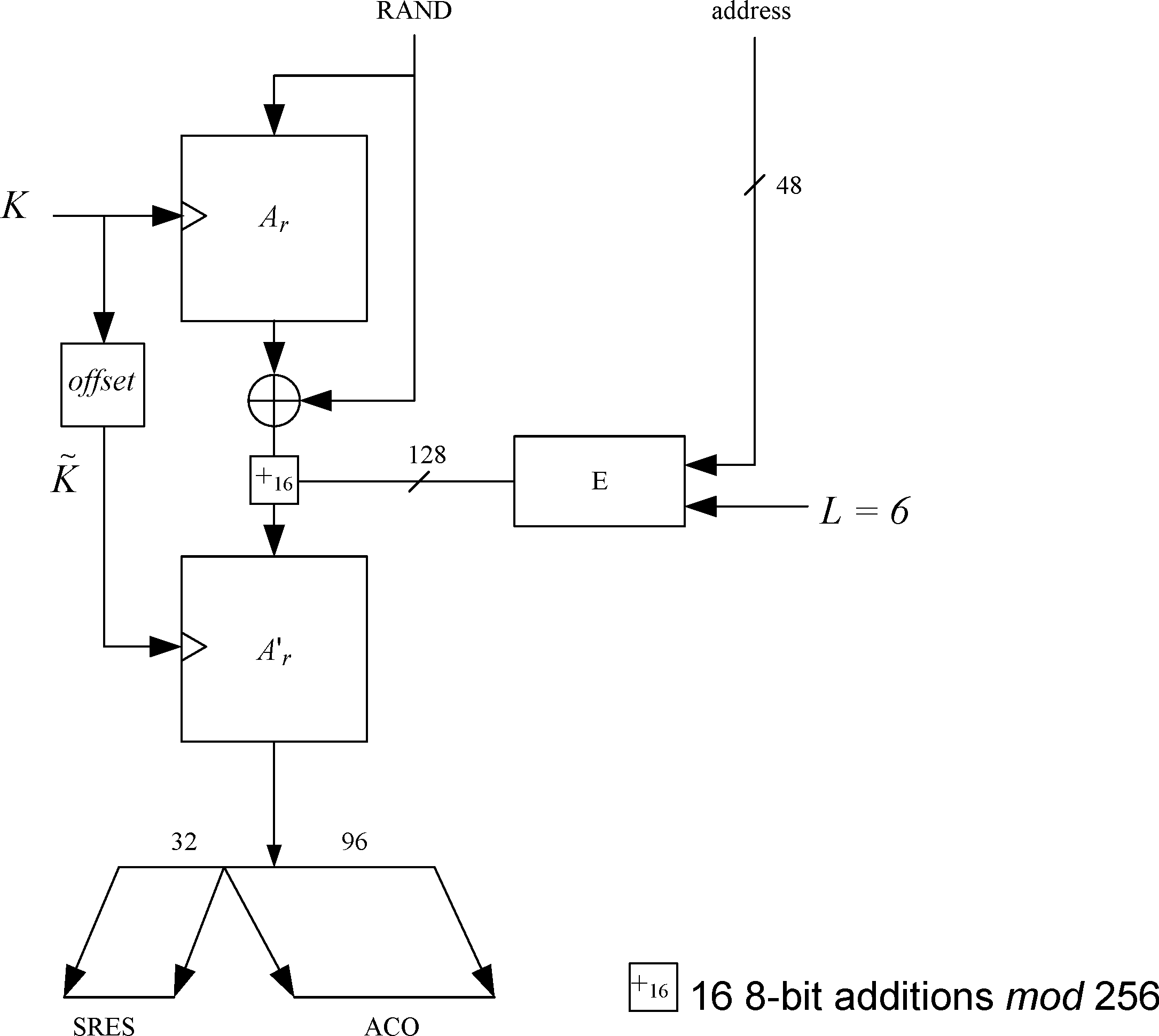
6.3. E2-key generation function for authentication
The key used for authentication shall be derived through the procedure that is shown in Figure 6.4. The figure shows two modes of operation for the algorithm. In the first mode, produces a 128-bit link key, , using a 128-bit RAND value and a 48-bit address. This mode shall be utilized when creating combination keys. In the second mode, produces a 128-bit link key, , using a 128-bit RAND value and an octet user PIN. The second mode shall be used to create the initialization key, and also when a temporary link key is to be generated.
When the initialization key is generated, the PIN is augmented with the BD_ADDR, see Section 3.2.1 for which address to use. The augmentation shall always start with the least significant octet of the address immediately following the most significant octet of the PIN. Since the maximum length of the PIN used in the algorithm cannot exceed 16 octets, it is possible that not all octets of BD_ADDR will be used.
This key generating algorithm again exploits the cryptographic function . for mode 1 (denoted ) is computed according to following equations:
where (for mode 1)
Let be the number of octets in the user PIN. The augmenting is defined by
where L' = min { 16, L+6 }.
Then, in mode 2, E2 (denoted E22) is
where

6.4. E3-key generation function for encryption
The ciphering key K_enc used by shall be generated by . The function is constructed using A'r as follows
where Hash is the hash function as defined by (EQ 13). The key length produced is 128 bits. However, before use within , the encryption key K_enc is shortened to the correct encryption key length, as described in Section 4.5. A block scheme of is depicted in Figure 6.5.
The value of COF is determined as specified by equation (EQ 3).

7. Secure Simple Pairing
The Secure Simple Pairing security functions and procedures are described in this section. In addition, a cryptographic analysis of each procedure is provided.
There are five phases of Secure Simple Pairing:
Phase 1: Public key exchange
Phase 2: Authentication stage 1
Phase 3: Authentication stage 2
Phase 4: Link key calculation
Phase 5: LMP Authentication and Encryption
Phases 1, 3, 4 and 5 are the same for all protocols whereas phase 2 (Authentication stage 1) is different depending on the protocol used. Distributed through these five phases are 13 steps as shown in Figure 7.1.

The terminology used in the security sections is defined in Table 7.1:
Term | Definition |
|---|---|
Cx | Commitment value from device X |
Cxi | ith commitment value from device X. Only used in the passkey entry protocol |
DHKey | Diffie Hellman key |
Ex | Check value from device X |
f1( ) | Used to generate the 128-bit commitment values Ca and Cb |
f2( ) | Used to compute the link key and possible other keys from the DHKey and random nonces |
f3( ) | Used to compute check values Ea and Eb in Authentication stage 2 |
g( ) | Used to compute numeric check values |
IOcapA | IO capabilities of device A |
IOcapB | IO capabilities of device B |
LK | Link Key |
Nx | Nonce (unique random value) from device X |
Nxi | ith nonce (unique random value) from device X. Only used in the passkey entry protocol |
PKx | Public Key of device X |
rx | Random value generated by device X |
rxi | Bit i of the random value rx. Only used in the passkey entry protocol |
SKx | Secret (Private) Key of device X |
Vx | Confirmation value on device X. Only used in the numeric compare protocol. |
X | BD_ADDR of device X |
7.1. Phase 1: Public key exchange
Initially, each device generates its own Elliptic Curve Diffie-Hellman (ECDH) public-private key pair (step 1). See Section 5.1 for recommendations on how frequently this key pair should be changed.
Pairing is initiated by the initiating device sending its public key to the receiving device (step 1a). The responding device replies with its own public key (step 1b). If the two public keys have the same X coordinate and neither is the debug key (see [Vol 4] Part E, Section 7.6.4), each device shall fail the pairing process. These public keys are not regarded as secret although they may identify the devices.
When both devices’ Controllers and Hosts support Secure Connections, the P-256 elliptic curve is used. When at least one device’s Controller or Host doesn’t support Secure Connections, the P-192 elliptic curve is used.

A device shall validate that any public key received from any BD_ADDR is on the correct curve (P-192 or P-256) - see Section 7.6.
7.2. Phase 2: Authentication stage 1
Authentication stage 1 has three different protocols: Numeric Comparison, Out-of-Band, and Passkey Entry. The Just Works association model shares the Numeric Comparison protocol and does not have a separate protocol.
The protocol is chosen based on the IO capabilities of the two devices.

The three protocols are described in the following sections.
7.2.1. Authentication stage 1: Numeric Comparison protocol
The Numeric Comparison protocol provides limited protection against active "man-in-the-middle" (MITM) attacks as an active man-in-the-middle will succeed with a probability of 0.000001 on each iteration of the protocol. Provided that there is no MITM at the time the pairing is performed, the shared Link Key that is generated is computationally secure from even a passive eavesdropper that may have been present during the pairing.
The sequence diagram of Authentication stage 1 for the Numeric Comparison protocol from the cryptographic point of view is shown in Figure 7.4.

After the public keys have been exchanged, each device selects a random 128-bit nonce (step 2). This value is used to mitigate replay attacks and shall be freshly generated with each instantiation of the pairing protocol. This value shall be generated using a random number generator that meets the requirements of Section 2.
Following this the responding device then computes a commitment to the two public keys that have been exchanged and its own nonce value (step 3c). This commitment is computed as a one-way function of these values and is transmitted to the initiating device (step 4). The commitment prevents an attacker from changing these values at a later time.
The initiating and responding devices then exchange their respective nonce values (steps 5 and 6) and the initiating device confirms the commitment (step 6a). A failure at this point indicates the presence of an attacker or other transmission error and causes the protocol to abort. The protocol may be repeated with or without the generation of new public-private key pairs, but, as stated above, new nonces must be generated if the protocol is repeated.
Assuming that the commitment check succeeds, the two devices each compute 6-digit confirmation values that are displayed to the user on their respective devices (steps 7a, 7b, and 8). The user is expected to check that these 6-digit values match and to confirm if there is a match. If there is no match, the protocol aborts and, as before, new nonces must be generated if the protocol is to be repeated.
An active MITM must inject its own key material into this process to have any effect other than denial-of-service. A simple MITM attack will result in the two 6-digit display values being different with probability 0.999999. A more sophisticated attack may attempt to engineer the display values to match, but this is thwarted by the commitment sequence. If the attacker first exchanges nonces with the responding device, it must commit to the nonce that it will use with the initiating device before it sees the nonce from the initiating device. If the attacker first exchanges nonces with the initiating device, it must send a nonce to the responding device before seeing the nonce from the responding device. In each case, the attacker must commit to at least the second of its nonces before knowing the second nonce from the legitimate devices. It therefore cannot choose its own nonces in such a way as to cause the display values to match.
7.2.2. Authentication stage 1: Out of Band protocol
The Out-of-Band protocol is used when authentication information has been received by at least one of the devices and indicated in the OOB Authentication Data Present parameter in the LMP IO capability exchange sequence. The mode in which the discovery of the peer device is first done in-band and then followed by the transmission of authentication parameters through OOB interface is not supported. The sequence diagram for Authentication stage 1 for Out of Band from the cryptographic point of view is shown in Figure 7.5.

Principle of operation: If both devices can transmit and/or receive data over an out-of-band channel, then mutual authentication will be based on the commitments of the public keys (Ca and Cb) exchanged OOB in Authentication stage 1. If OOB communication is possible only in one direction, then authentication of the device receiving the OOB communication will be based on that device knowing a random number r sent via OOB. In this case, r must be secret: r can be created afresh every time, or access to the device sending r must be restricted. If r is not sent by a device, it is assumed to be 0 by the device receiving the OOB information in step 4a or 4b.
Roles of A and B: The OOB Authentication stage 1 protocol is symmetric with respect to the roles of A and B. It does not require that device A always will initiate pairing and it automatically resolves asymmetry in the OOB communication, e.g. in the case when one of the devices has an NFC tag and can only transmit OOB.
Order of steps: The public key exchange must happen before the verification step 5. In the diagram the in-band public key exchange between the devices (step 1) is done before the OOB communication (step 4). But when the pairing is initiated by an OOB interface, public key exchange will happen after the OOB communication (step 1 will be between steps 4 and 5).
Values of ra and rb: Since the direction of the peer's OOB interface cannot be verified before the OOB communication takes place, a device should always generate and if possible transmit through its OOB interface a random number r to the peer. Each device applies the following rules locally to set the values of its own r and the value of the peer's r:
Initially, r of the device is set to a random number and r of the peer is set to 0 (step 2).
If a device has received OOB, it sets the peer's r value to what was sent by the peer (Step 5).
If the remote device's OOB Authentication Data parameter sent in the LMP IO capabilities exchange sequence is set to No OOB Data Received, it sets its own r value to 0 (Step 5)
These rules ensure that when entering Authentication stage 2, both A and B have the same values for ra and rb if OOB communication took place.
7.2.3. Authentication stage 1: Passkey Entry protocol
The Passkey Entry protocol is used when LMP IO capability exchange sequence indicates that Passkey Entry shall be used.
The sequence diagram for Authentication stage 1 for Passkey Entry from the cryptographic point of view is shown in Figure 7.6.

The user inputs an identical Passkey into both devices. Alternately, the Passkey may be generated and displayed on one device, and the user then inputs it into the other (step 2). This short shared key will be the basis of the mutual authentication of the devices. The Passkey should be generated randomly during each pairing procedure and not be reused from a previous procedure. Static Passkeys should not be used since they can compromise the security of the link.
Steps 3 to 8 are repeated 20 times since a 6-digit Passkey is 20 bits (999999=0xF423F). If the device allows a shorter passkey to be entered, it shall be prefixed with zeros (e.g. “1234” is equivalent to “001234”).
In Steps 3 to 8, each side commits to each bit of the Passkey, using a long nonce (128 bits), and sending the hash of the nonce, the bit of the Passkey, and both public keys to the other party. The parties then take turns revealing their commitments until the entire Passkey has been mutually disclosed. The first party to reveal a commitment for a given bit of the Passkey effectively reveals that bit of the Passkey in the process, but the other party then has to reveal the corresponding commitment to show the same bit value for that bit of the Passkey, or else the first party will then abort the protocol, after which no more bits of the Passkey are revealed.
This "gradual disclosure" prevents leakage of more than 1 bit of un-guessed Passkey information in the case of a MITM attack. A MITM attacker with only partial knowledge of the Passkey will only receive one incorrectly-guessed bit of the Passkey before the protocol fails. Hence, a MITM attacker who engages first one side, then the other will only gain an advantage of at most two bits over a simple brute-force guesser, making the probability of success 0.000004 instead of 0.000001.
The long nonce is included in the commitment hash to make it difficult to brute-force even after the protocol has failed. The public Diffie-Hellman values are included to tie the Passkey protocol to the original ECDH key exchange, to prevent a MITM from substituting the attacker's public key on both sides of the ECDH exchange in standard MITM fashion.
At the end of this stage, Na is set to Na20 and Nb is set to Nb20 for use in Authentication stage 2.
7.3. Phase 3: Authentication stage 2
The second stage of authentication then confirms that both devices have successfully completed the exchange. This stage is identical in all three protocols and is shown in Figure 7.7.
Each device computes a new confirmation value that includes the previously exchanged values and the newly derived shared key (step 9). The initiating device then transmits its confirmation value which is checked by the responding device (step 10). If this check fails, it indicates that the initiating device has not confirmed the pairing, and the protocol shall be aborted. The responding device then transmits its confirmation value which is checked by the initiating device (step 11). A failure indicates that the responding device has not confirmed the pairing and the protocol should abort.

7.4. Phase 4: Link key calculation
Once both sides have confirmed the pairing, a link key is computed from the derived shared key and the publicly exchanged data (step 12). The nonces ensure the freshness of the key even if long-term ECDH values are used by both sides. This link key is used to maintain the pairing.
When computing the link key both parties shall input the parameters in the same order (shown in Figure 7.8) to ensure that both devices compute the same key: Nc is whichever of Na and Nb was generated by the Central and Np is the other, while BD_ADDR_C and BD_ADDR_P are the addresses of the Central and Peripheral respectively.

7.5. Phase 5: LMP authentication and encryption
The final phase in Secure Simple Pairing consists of authentication and generation of the encryption key. This is the same as the final steps in legacy pairing.
7.6. Elliptic curve definition
Secure Simple Pairing supports two elliptic curves: P-192 and P-256.
Secure Simple Pairing uses the FIPS P-192 and P-256 curves defined in FIPS 186-45. Elliptic curves are specified by p, a, b and are of the form:
E: y2 = x3 + ax + b (mod p)
In NIST P-192 and P-256, a is -3 and the following parameters are given:
The prime modulus p, order r, base point x-coordinate Gx, base point y-coordinate Gy.
The integers p and r are given in decimal form; bit strings and field elements are given in hex.
For P-192: | ||
p | = | 6277101735386680763835789423207666416083908700390324961279 |
r | = | 6277101735386680763835789423176059013767194773182842284081 |
b | = | 64210519 e59c80e7 0fa7e9ab 72243049 feb8deec c146b9b1 |
Gx | = | 188da80e b03090f6 7cbf20eb 43a18800 f4ff0afd 82ff1012 |
Gy | = | 07192b95 ffc8da78 631011ed 6b24cdd5 73f977a1 1e794811 |
The function P192 is defined as follows. Given an integer u, 0 < u < r, and a point V on the curve E, the value P192(u,V) is computed as the x-coordinate of the uth multiple uV of the point V.
The private keys shall be between 1 and r÷2, where r is the order of the Abelian group on the elliptic curve (i.e., between 1 and 2192÷2).
For P-256: | ||
p | = | 115792089210356248762697446949407573530086143415290314195533631308867097853951 |
r | = | 115792089210356248762697446949407573529996955224135760342422259061068512044369 |
b | = | 5ac635d8 aa3a93e7 b3ebbd55 769886bc 651d06b0 cc53b0f6 3bce3c3e 27d2604b |
Gx | = | 6b17d1f2 e12c4247 f8bce6e5 63a440f2 77037d81 2deb33a0 f4a13945 d898c296 |
Gy | = | 4fe342e2 fe1a7f9b 8ee7eb4a 7c0f9e16 2bce3357 6b315ece cbb64068 37bf51f5 |
The function P256 is defined as follows. Given an integer u, 0 < u < r, and a point V on the curve E, the value P256(u, V) is computed as the x-coordinate of the uth multiple uV of the point V.
The private keys shall be between 1 and r÷2, where r is the order of the Abelian group on the elliptic curve (i.e., between 1 and 2256÷2).
A valid public key Q = (XQ, YQ) is one where XQ and YQ are both in the range 0 to p - 1 and satisfy the equation (YQ)2 = (XQ)3 + aXQ + b (mod p) in the relevant curve's finite field.
A device can validate a public key by directly checking the curve equation, by implementing elliptic curve point addition and doubling using formulas that are valid only on the correct curve, or by other means.
7.7. Cryptographic function definitions
In addition to computing the Elliptic Curve Diffie Hellman key, the Numeric Comparison, Out-of-Band and Passkey Entry protocols require four cryptographic functions. These functions are known as f1, g, f2 and f3.
f1 is used to generate the 128-bit commitment values Ca and Cb
g is used to compute the 6-digit numeric check values
f2 is used to compute the link key and possible other keys from the DHKey and random nonces
f3 is used to compute check values Ea and Eb in Authentication stage 2.
The basic building block for these functions is based on SHA-256, specified in [FIPS PUB 180-4] (http://dx.doi.org/10.6028/NIST.FIPS.180-4).
Inside the f1, g, f2, and f3 cryptographic functions, when a multi-octet integer input parameter is used as input to the SHA-256 and HMAC-SHA-256 functions, the most significant octet of the integer parameter shall be the first octet of the stream and the least significant octet of the integer parameter shall be the last octet of the stream. The output of the f1, g, f2, and f3 cryptographic functions is a multi-octet integer where the first octet out of SHA-256 and HMAC-SHA-256 shall be the MSB and the last octet shall be the LSB of that parameter.
7.7.1. The Secure Simple Pairing commitment function f1
The commitments are computed with function f1. The definition of the Secure Simple Pairing commitment function makes use of the MAC function HMAC based on SHA-256x, which is denoted as HMAC-SHA-256X with 128-bit key X.
The inputs to the Secure Simple Pairing function f1 are specified in Table 7.2.
Input | Bits with P-192 | Bits with P-256 |
|---|---|---|
U | 192 | 256 |
V | 192 | 256 |
X | 128 | 128 |
Z | 8 | 8 |
Z is zero (i.e., 8 bits of zeros) for Numeric Comparison and OOB protocol. In the Passkey protocol the most significant bit of Z is set equal to one and the least significant bit is made up from one bit of the passkey e.g. if the passkey bit is 1 then Z = 0x81 and if the passkey bit is 0 then Z = 0x80.
The output of the Secure Simple Pairing f1 function is:
f1(U, V, X, Z) = HMAC-SHA-256X (U || V || Z) ÷ 2128 |
The inputs to f1 are different depending on the different protocols as specified in Table 7.3.
Numeric Comparison | Out-Of-Band | Passkey Entry |
|---|---|---|
Ca = f1(PKax, PKbx, Na, 0) | Ca = f1(PKax, PKax, ra, 0) | Cai = f1(PKax, PKbx, Nai, rai) |
Cb = f1(PKbx, PKax, Nb, 0) | Cb = f1(PKbx, PKbx, rb, 0) | Cbi = f1(PKbx, PKax, Nbi, rbi) |
where PKax denotes the x-coordinate of the public key PKa of A. Similarly, PKbx denotes the x-coordinate of the public key PKb of B. Nai is the nonce value of ith round. For each round Nai value is a new 128 bit number. Similarly, rai is one bit value of the passkey expanded to 8 bits (either 0x80 or 0x81).
Na and Nb are nonces from Devices A and B. ra and rb are random values generated by devices A and B.
7.7.2. The Secure Simple Pairing numeric verification function g
The Secure Simple Pairing g function is defined as follows:
The inputs to the Secure Simple Pairing function g are specified in Table 7.4.
Input | Bits with P-192 | Bits with P-256 |
|---|---|---|
U | 192 | 256 |
V | 192 | 256 |
X | 128 | 128 |
Y | 128 | 128 |
The output of the Secure Simple Pairing g function is:
g(U, V, X, Y) = SHA-256(U || V || X || Y) mod 232 |
The numeric verification value is taken as six least significant digits of the 32-bit integer g(PKax, PKbx, Na, Nb) where PKax denotes the x-coordinate of the public key PKa of A and PKbx denotes the x-coordinate of the public key PKb of B.
Output of SHA-256 is truncated to 32 bits by taking the least significant 32 bits of the output of SHA-256. This value is converted to decimal numeric value. The checksum used for numeric comparison is the least significant six digits.
Compare Value = g (U, V, X, Y) mod 106 |
For example, if output = 0x 01 2e b7 2a then decimal value = 19838762 and the checksum used for numeric comparison is 838762.
7.7.3. The Secure Simple Pairing key derivation function f2
The definition of the Secure Simple Pairing key derivation function makes use of the MAC function HMAC based on SHA-256, which is denoted as HMAC-SHA-256W with 192-bit or 256-bit key W.
The inputs to the Secure Simple Pairing function f2 are specified in Table 7.5.
Input | Bits with P-192 | Bits with P-256 |
|---|---|---|
W | 192 | 256 |
N1 | 128 | 128 |
N2 | 128 | 128 |
keyID | 32 | 32 |
A1 | 48 | 48 |
A2 | 48 | 48 |
The string "btlk" is mapped into a keyID using ASCII as 0x62746C6B.
The output of the Secure Simple Pairing f2 function is:
f2(W, N1, N2, KeyID, A1, A2) = HMAC-SHA-256W (N1 || N2 || KeyID || A1 || A2) ÷ 2128 |
The output of f2 is taken as the 128 most significant (leftmost) bits of the output of HMAC-SHA-256.
The link key is then calculated as:
LK = f2(DHKey, Nc, Np, "btlk", BD_ADDR_C, BD_ADDR_P) |
Nc is whichever of N1 and N2 was generated by the Central and sent to the Peripheral; Np is the other.
7.7.4. The Secure Simple Pairing check function f3
The definition of the Secure Simple Pairing f3 check function makes use of the MAC function HMAC based on SHA-256, which is denoted as HMAC-SHA-256W with 192-bit or 256-bit key W.
The inputs to the Secure Simple Pairing function f3 are specified in Table 7.6.
Input | Bits with P-192 | Bits with P-256 |
|---|---|---|
W | 192 | 256 |
N1 | 128 | 128 |
N2 | 128 | 128 |
IOcap | 24 | 24 |
A1 | 48 | 48 |
A2 | 48 | 48 |
IOcap is three octets with the most significant octet as the Authentication Requirements parameter, the middle octet as the LMP Out-of-Band Authentication Data parameter, and the least significant octet as the LMP IO capability parameter.
The output of the Secure Simple Pairing f3 function is:
The output of f3 is taken as the 128 most significant (leftmost) bits of the output of HMAC-SHA-256. The check values are computed with function f3. The inputs to f3 are different depending on the different protocols, as specified in Table 7.7.
Numeric Comparison | Out-Of-Band | Passkey Entry |
|---|---|---|
Ea = f3(DHKey, Na, Nb, 0, IOcapA, A, B) | Ea = f3( DHKey, Na, Nb, rb, IOcapA, A, B) | Ea = f3( DHKey, Na20, Nb20, rb, IOcapA, A, B) |
Eb = f3(DHKey, Nb, Na, 0, IOcapB, B, A) | Eb = f3(DHKey, Nb, Na, ra, IOcapB, B, A) | Eb = f3(DHKey, Nb20, Na20, ra, IOcapB, B, A) |
DHKey denotes the shared secret Diffie-Hellman Key computed as P192(SKa, PKb) or P256(SKa, PKb) by A and as P192(SKb, PKa) or P256(SKb, PKa) by B. IOcapA denotes the IO capability data of A and IOcapB denotes the IO capability data of B. In Passkey Entry, the data ra and rb are 6-digit passkey values which are expressed as a 128-bit integer. For instance, if the 6-digit value of ra is 131313, then
R = 0x 00 00 00 00 00 00 00 00 00 00 00 00 00 02 00 f1.
The input A is the BD_ADDR of device A and the input B is the BD_ADDR of device B.
7.7.5. [This section is no longer used]
7.7.6. The AES encryption key generation function h3
AES encryption keys are created using the AES encryption key generation function h3. The definition of the AES encryption key generation function makes use of the MAC function HMAC based on SHA-256, which is denoted as HMAC-SHA-256T with 128-bit key T.
The inputs to function h3 are specified in Table 7.8.
Input | Bits with P-256 |
|---|---|
T | 128 |
keyID | 32 |
A1 | 48 |
A2 | 48 |
ACO | 64 |
A1 is the BD_ADDR of the Central. A2 is the BD_ADDR of the Peripheral. ACO is the 64 bit ACO output from h5. T is the 128 bit Bluetooth Link Key derived from f2.
The string “btak” (Bluetooth AES Key) is mapped into a keyID using ASCII as 0x6274616B.
The output of function h3 is:
h3(W, keyID, A1, A2, ACO) = HMAC-SHA-256T(KeyID || A1 || A2 || ACO) ÷ 2128
The output of h3 is taken as the 128 most significant (leftmost) bits of the output of HMAC-SHA-256.
7.7.7. The Device authentication key generation function h4
With Secure Connections, a device authentication key is created using function h4. The definition of the device authentication key generation function makes use of the MAC function HMAC based on SHA-256, which is denoted as HMAC-SHA-256T with 128-bit key T.
The inputs to function h4 are specified in Table 7.9.
Input | Bits with P-256 |
|---|---|
T | 128 |
keyID | 32 |
A1 | 48 |
A2 | 48 |
A1 is the BD_ADDR of the Central. A2 is the BD_ADDR of the Peripheral. T is the 128 bit Bluetooth Link Key derived from f2.
The string “btdk” (Bluetooth Device Key) is mapped into a keyID using ASCII as 0x6274646B.
The output of function h4 is:
h4(W, KeyID, A1, A2) = HMAC-SHA-256T(KeyID || A1 || A2) ÷ 2128
The output of h4 is taken as the 128 most significant (leftmost) bits of the output of HMAC-SHA-256.
7.7.8. The Device authentication confirmation function h5
With Secure Connections, device authentication confirmation values are created using function h5. The definition of the device authentication confirmation function makes use of the MAC function HMAC based on SHA-256, which is denoted as HMAC-SHA-256S with 128-bit key S.
The inputs to function h5 are specified in Table 7.10.
Input | Bits with P-256 |
|---|---|
S | 128 |
R1 | 128 |
R2 | 128 |
R1 is the 128 bit random number (AU_RAND_C) from the Central during the Link Manager device authentication sequence. R2 is the 128 bit random number from the Peripheral (AU_RAND_P) during the Link Manager device authentication sequence. S is the 128-bit Bluetooth Device Authentication Key derived from h4.
The output of function h5 is:
h5(W, R1, R2 ) = HMAC-SHA-256S(R1 || R2) ÷ 2128
The output of h5 is taken as the 128 most significant (leftmost) bits of the output of HMAC-SHA-256. The first 32 bits (leftmost) become the SRES_C. The next 32 bits become the SRES_P. The final 64 bits become the Authentication Ciphering Offset (ACO), which is used in h3 and as the IV for Encryption Start for the encryption nonce.
8. [This section is no longer used]
9. AES-CCM encryption for BR/EDR
The Baseband provides security using Counter with CBC-MAC (CCM) as defined in IETF RFC 3610 (http://www.ietf.org/rfc/rfc3610.txt) with a modification to the B1 counter mode block format that omits the length of the additional authenticated data. The description of the algorithm can also be found in the NIST Special Publication 800-38C (http://csrc.nist.gov/publications/PubsSPs.html).
Using the notation in [4], CCM has two size parameters, M and L.
The Baseband defines these to be:
M = 4; indicating that the MIC length is 4 octets (32 bits)
Size of M represents a trade-off between message expansion and the probability that an attacker can undetectably modify a message.
L = 2; indicating that the Length field is 2 octets (16 bits)
Size of L requires a trade-off between the maximum message size and the size of the Nonce.
9.1. Nonce formats
All of the parameters in the nonce are unique per logical transport. The nonce will be 13 octets and will have two formats. The first format is called the payload counter format and is used for ACL packets on the primary LT_ADDR. The second format is called the clock format and is used for eSCO packets.
The reason for two formats has to do with two factors: potential security attacks and synchronization. Since ACL packets on the primary LT_ADDR carry protocol, they are susceptible to attacks that eSCO packets (only data) are not.
The descriptions of the two nonce formats are provided in Table 9.1.
Octet | Field | Octets | Payload Counter Format Description | Clock Format Description |
|---|---|---|---|---|
0 | Nonce0 | 1 | PayloadCounter[7:0] | CLK[8:1] |
1 | Nonce1 | 1 | PayloadCounter[15:8] | CLK[16:9] |
2 | Nonce2 | 1 | PayloadCounter[23:16] | CLK[24:17] |
3 | Nonce3 | 1 | PayloadCounter[31:24] | Bits 2-0: CLK[27:25] Bits 7-3: dayCounter[4:0] |
4 | Nonce4 | 1 | Bits 3-0: PayloadCounter[35:32] Bit 4: zero-length ACL-U continuation packet (1=zero-length ACL-U continuation packet, 0=otherwise) Bit 5: direction (0=Central to Peripheral, 1=Peripheral to Central) Bits 7-6: nonceType = 0b00 (ACL) | Bits 5-0: dayCounter[10:5] Bits 7-6: nonceType = 0b01 (eSCO) |
5 | Nonce5 | 1 | IV[7:0] | |
6 | Nonce6 | 1 | IV[15:8] | |
7 | Nonce7 | 1 | IV[23:16] | |
8 | Nonce8 | 1 | IV[31:24] | |
9 | Nonce9 | 1 | IV[39:32] | |
10 | Nonce10 | 1 | IV[47:40] | |
11 | Nonce11 | 1 | IV[55:48] | |
12 | Nonce12 | 1 | IV[63:56] | |
In the payload counter format, the PayloadCounter starts at zero for the first encrypted packet in each direction after encryption is started or resumed and increments by one every time an encrypted payload including zero-length payloads is accepted by the remote device.
Note
Note: It is possible that when encryption is being enabled or resumed, a packet may first get transmitted unencrypted and then get retransmitted encrypted. In such a case, the PayloadCounter gets incremented by one when the encrypted retransmission of the packet gets accepted by the remote device.
Bit 4 of Octet 4 shall be set to 1 for a zero length ACL-U continuation packet (see [Vol 2] Part B, Section 7.6.2.2), otherwise it shall be set to 0.
In the clock format, the Central's clock (CLK) used for the nonce shall be the value in the first slot of the packet. After a new ACL connection has been established or a role switch has been successfully performed and when eSCO is successfully established for the first time then the dayCounter value shall be initialized to:
1 if CLK27 in the first clock format nonce is 0, and initialization procedure 2 (see [Vol 2] Part B, Section 8.6.3) is used
0 otherwise.
After the dayCounter has been initialized, it shall increment by one every time the Central's clock (CLK) rolls over to 0x0000000 (approximately every 23.3 hours).
Note
Note: When Security Mode 4 is in use, eSCO will not be established before encryption is started.
The IV is an 8 octet field. For encryption start, all octets of the IV are from the ACO output of the last execution of h5 prior to the start of encryption. Multiple device authentications may occur prior to starting encryption but only the ACO of the last device authentication is used. After an encryption resume, all 8 octets of the IV are from the EN_RAND sent by the device initiating the encryption pause (see [Vol 2] Part C, Section 4.2.5.5). An encryption pause and resume will be required prior to the PayloadCounter or dayCounter rolling over in order to keep the nonce fresh for an encryption key.
Octet | IV for Encryption Start | IV After Resume Encryption |
|---|---|---|
0 | ACO[0] | EN_RAND[0] |
1 | ACO[1] | EN_RAND[1] |
2 | ACO[2] | EN_RAND[2] |
3 | ACO[3] | EN_RAND[3] |
4 | ACO[4] | EN_RAND[4] |
5 | ACO[5] | EN_RAND[5] |
6 | ACO[6] | EN_RAND[6] |
7 | ACO[7] | EN_RAND[7] |
9.2. Counter mode blocks
For calculating the MIC, the payload is broken into two or more counter mode blocks. The CCM specification refers to these blocks as blocks B0 – Bn. B0 applies to the nonce, B1 applies to the associated data {that is packet header and payload header} and additional B blocks are generated as needed for authentication of the payload body.
Offset (octets) | Field | Size (octets) | Value | Description |
|---|---|---|---|---|
0 | Flags | 1 | 0x49 | As per the CCM specification |
1 | Nonce | 13 | variable | The nonce as described in Section 9.1. Nonce0 shall have offset 1. Nonce12 shall have offset 13. |
14 | Length[MSO] | 1 | variable | The most significant octet of the length of the payload body |
15 | Length[LSO] | 1 | variable | The least significant octet of the length of the payload body |
Offset | Field | Size (octets) | Value | Description |
|---|---|---|---|---|
0 | Packet_Header [MSO] | 1 | Variable | The most significant octet of the packet header: Bit 0: 0 (ARQN masked) Bit 1: 0 (SEQN masked) Bit 7 – Bit 2: 0b000000 |
1 | Packet_Header [LSO] | 1 | Variable | The least significant octet of the packet header: Bit 2 – Bit 0: LT_ADDR Bit 6 – Bit 3: TYPE Bit 7: 0 (FLOW masked) |
2 | Payload_Header | 1 | Variable | The payload header: Bit 1 – Bit 0: LLID Bit 2: 0 (FLOW masked) Bit 7 – Bit 3: 0b00000 |
3 | Padding | 13 | 0x00, 0x00, 0x00, 0x00, 0x00, 0x00, 0x00, 0x00, 0x00, 0x00, 0x00, 0x00, 0x00 | These octets are only used to pad the block. They are not part of the packet and never transmitted. |
9.3. Encryption blocks
The CCM algorithm uses the Ai blocks to generate a keystream that is used to encrypt the MIC and payload body. Block A0 is always used to encrypt and decrypt the MIC, when present. Block A1 is always used to encrypt and decrypt the first 16 octets of the payload body. Subsequent blocks are always used to encrypt and decrypt the rest of the payload body as needed.
Offset (octets) | Field | Size (octets) | Value | Description |
|---|---|---|---|---|
0 | Flags | 1 | 0x01 | As per the CCM specification |
1 | Nonce | 13 | variable | The nonce as described in Section 9.1. Nonce0 shall have offset 1. Nonce12 shall have offset 13. |
14 | i[MSO] | 1 | variable | The most significant octet of the counter i |
15 | i[LSO] | 1 | variable | The least significant octet of the counter i |
9.4. Encryption key size reduction
When the devices have negotiated a key size shorter than the maximum length, the key will be shortened by replacing the appropriate number of least significant octets of the key with 0x00.
For example, if a 128-bit encryption key is
0x12345678_9ABCDEF0_12345678_9ABCDEF0
and it is reduced to 7 octets (56 bits), then the resulting key is
0x12345678_9ABCDE00_00000000_00000000.
9.5. Repeated MIC failures
Anytime the MIC check fails and the CRC passes on a given packet, it is considered an authentication failure. No more than three authentication failures shall be permitted during the lifetime of an encryption key with a given IV. The third authentication failure shall initiate an encryption key refresh (see [Vol 2] Part C, Section 4.2.5.8). If a fourth authentication failure occurs prior to the encryption key refresh procedure completing, the link shall be disconnected with reason code Connection Rejected Due to Security Reasons (0x0E).
Note
Note: The MIC is not checked when the CRC is invalid.
1The reflection attack actually forms no threat because all service requests are dealt with on a FIFO basis. When preemption is introduced, this attack is potentially dangerous.
2Another appropriate value larger than 1 may be used.
3In this section and in Figure 6.3, the operator +16 denotes addition mod 256 of each of the 16 octets separately.
4The constants are the largest primes below 257 for which 10 is a primitive root.