Bluetooth® Mesh Remote Provisioning
Technical Overview
1.1.1 The Provisioning Protocol
1.1.3 The Stages of Provisioning
1.2 Device Keys and the Commissioning Process
2.1.1 Multi-hop Device Provisioning
2.1.3 Dynamic Device Composition
2.2.2 The Stages of Remote Provisioning
2.2.3 The Node Provisioning Protocol Interface
2.2.4 Remote Provisioning and Security
| Release : | 1.0.0 |
| Document Version : | 1.0 |
| Last updated : | September 19, 2023 |
| Authors : |
Martin Woolley, Bluetooth SIG |
|
Version |
Date |
Author |
Changes |
|
1.0.0 |
September 19, 2023 |
Martin Woolley, Bluetooth SIG |
Initial version |
|
Note The Bluetooth Mesh Profile Specification has been renamed and is now called the Bluetooth Mesh Protocol Specification. References in this and related papers will use this name when referring to the version 1.1 specification but continue to refer to the version 1.0 specification as the Bluetooth Mesh Profile Specification. |
1. Background
The remote provisioning feature was introduced in version 1.1 of the Bluetooth® Mesh protocol specification. To fully appreciate its capabilities and benefits, it is necessary to understand certain aspects of Bluetooth Mesh version 1.0. This section provides context and background which will support the review of remote provisioning which follows.
1.1 Provisioning
A device becomes a member of a Bluetooth Mesh network through the act of provisioning. Provisioning is a procedure which is carried out by a commissioner using a device or application called a Provisioner. Provisioning a device results in it possessing certain critical items of data, including the network’s primary network key (NetKey) and a unique range of contiguous unicast addresses assigned to the device’s elements. The device undergoing provisioning is called the Provisionee.
Originally, as defined in version 1.0 of the Bluetooth Mesh profile specification, the Provisioner had to be in direct radio range of the Provisionee.
1.1.1 The Provisioning Protocol
A protocol solely used for the purpose of provisioning is called the provisioning protocol. At version 1.0 of the Bluetooth® Mesh profile specification, the protocol included 10 distinct types of PDU.
1.1.2 Provisioning Bearers
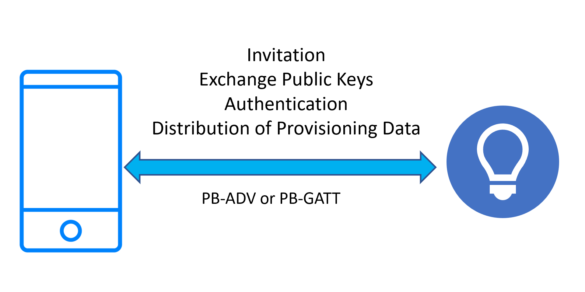
In Bluetooth® Mesh version 1.0, the provisioning protocol could operate using either Bluetooth LE advertising packets or GATT procedures over a connection. The use of advertising packets as containers for provisioning protocol PDUs is known as the PB-ADV bearer. Using GATT for provisioning is known at the PB-GATT bearer.
1.1.3 The Stages of Provisioning
Provisioning progresses through the following five stages:
- Beaconing
- Invitation
- Exchange public keys
- Authentication
- Distribution of provisioning data
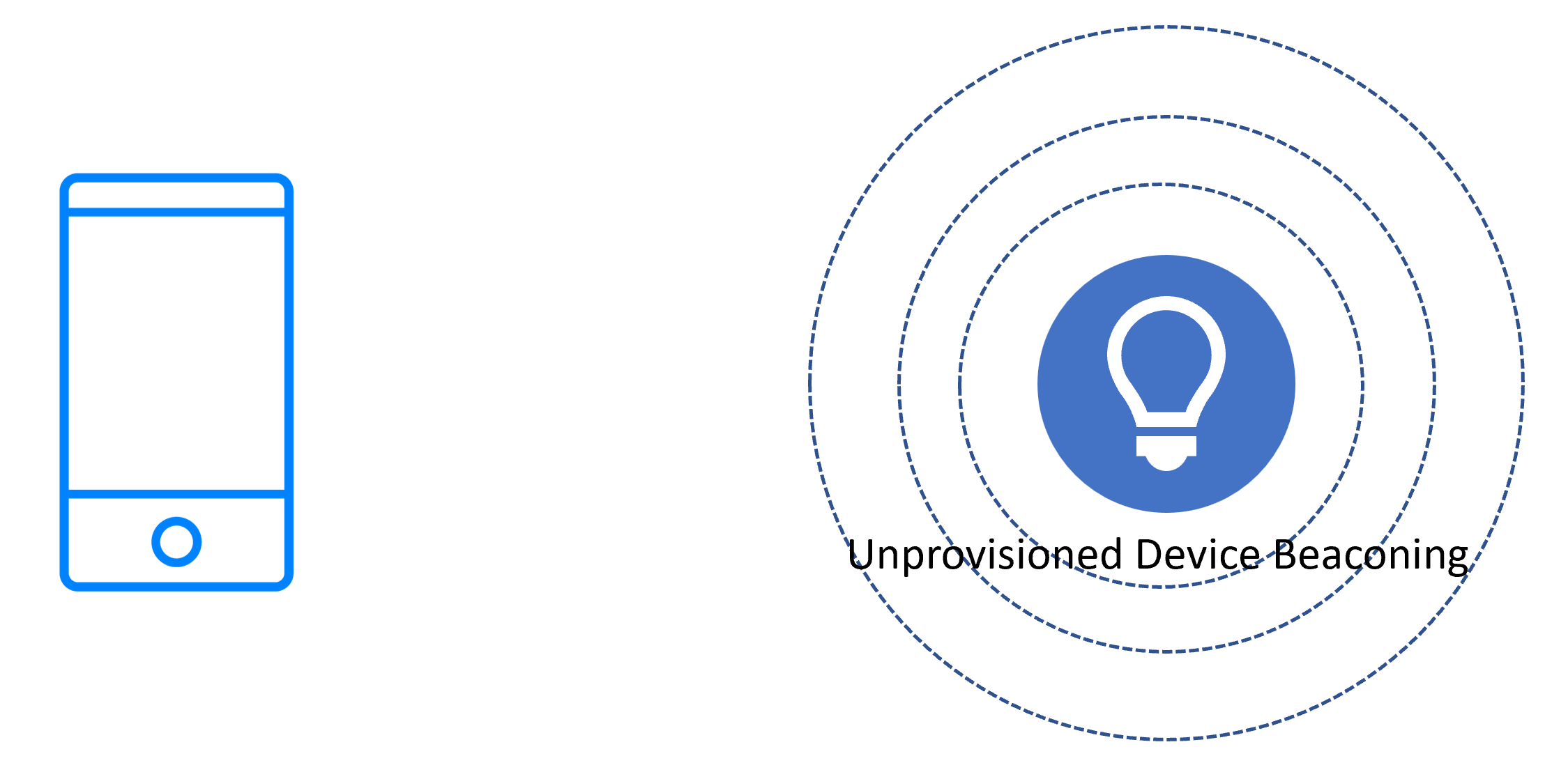
1.1.3.1 Beaconing
A new device which is ready to be provisioned signals its availability by broadcasting Bluetooth LE advertising packets of one or two possible types, depending on the bearer(s) that the device supports. If the PB-ADV bearer is supported then unprovisioned device beacons are broadcasted as non-connectable and non-scannable, undirected Bluetooth LE advertising packets. If PB-GATT is supported, then connectable advertising packets that contain the UUID of the mesh provisioning service are broadcast. If both bearers are supported, then these two forms of advertising are interleaved.
In either case, the beaconing data includes the Device UUID of the unprovisioned device. The Device UUID is a unique identifier for the device which does not change over a lifetime of a physical or software product and is usually assigned in the factory.
1.1.3.2 Invitation
The Provisioner scans for unprovisioned device beacons and/or connectable advertisements indicating support for the GATT mesh provisioning service and establishes a session (called as link) on either a PB-ADV or PB-GATT bearer instance with a selected unprovisioned device. It then sends a Provisioning Invite PDU to initiate the provisioning process. The device, now known as the Provisionee, responds with a Provisioning Capabilities PDU that contains information which is used to control the next steps of the provisioning process. The Provisioner constructs a Provisioning Start PDU with contents that are based on this information and sends it.
1.1.3.3 Exchange Public Keys
Elliptic Curve Cryptography (ECC) is used to allow the NetKey to be securely transferred from the Provisioner to the unprovisioned device. ECC is an approach to public key cryptography based upon the mathematical properties of elliptic curves. It requires relatively small key sizes and is well suited for use by devices whose computing power is limited.
The Provisioner generates an ephemeral public/private key pair and sends its public key to the Provisionee over the Bluetooth link using the selected bearer. The Provisionee may either send its public key over the same link or, for better security, provide it using an out of band (OOB) method such as via a QR code or using Near Field Communications (NFC). The Provisionee’s public/private key pair may have been statically defined or is dynamically generated.
Once in possession of each other’s public keys, a key agreement protocol allows a shared secret to be calculated and, from this, a session key is calculated. The session key is then used to secure the NetKey transfer. The shared secret is also used to calculate Confirmation Key used in authentication step and the Device Key of the device.
1.1.3.4 Authentication
Provisioning will often take place in a location where there are many Bluetooth® Mesh devices. To ensure that the device being provisioned is the one intended and to safeguard against man-in-the-middle (MITM) attacks, the provisioning procedure includes an authentication step.
Authentication can take various forms, and one is selected according to the capabilities of the unprovisioned device, which the Provisioner is informed of via a Provisioning Capabilities PDU received during the invitation stage.
The Output OOB method involves the unprovisioned device outputting a numeric or text value using an action it supports. For example, it might flash an LED or beep a number of times. The output number is input to the Provisioner, and a confirmation procedure checks that the expected value was entered.
If the Input OOB method is used, the Provisioner generates a random number which is input to the unprovisioned device using a suitable action (e.g., pressing a button a number of times) and verified by the confirmation procedure.
The Static OOB approach involves a fixed value, possibly printed on the device or on its packaging, which is entered into the Provisioner and used in the confirmation procedure.
Whichever method is used, the result is to either succeed or fail to authenticate the device being provisioned and inform the user of the outcome.
1.1.3.5 Distribution of Provisioning Data
After successful authentication, a session key is generated and used to encrypt and authenticate the Provisioning Data PDU sent over the link. The Provisioner sends data, which includes the primary NetKey and a unique unicast address for the primary element of the device. The device can now be said to have been provisioned.
|
Figure 2 – Stages 2-5 of provisioning process |
1.2 Device Keys and the Commissioning Process
The Bluetooth® Mesh security system involves a number of security keys, each with a particular role to play.
Network keys are used in the encryption and authentication of fields in PDUs that relate to the network layer. Possession of a particular network key, evidenced by its use in this way, signifies a node’s membership of the subnet that the network key belongs to.
Application keys are used in the encryption and authentication of fields in PDUs relating to higher layers of the Bluetooth Mesh protocol stack and generally are issued to devices that are part of a particular building system such as lighting or air-conditioning.
A node may possess several network keys and several application keys.
All nodes have a single device key (DevKey). This key is used to secure messages belonging to specific models, usually related to device configuration. A node computes its DevKey when it is provisioned. The DevKey is never transferred over the network.
When a Bluetooth® Mesh network is initially created, especially in the world of smart buildings, the devices are usually installed, provisioned, and configured by a team of contractors who eventually hand over the completed network to the building owner. For optimal security, at this point it is desirable that the building owner has the option to change the security keys in each node in the network.
Bluetooth Mesh 1.0 defines the Key Refresh procedure, which allows network keys and application keys to be changed across the whole network. There is no procedure for changing device keys defined in Bluetooth Mesh 1.0.
1.3 Node Addresses
Bluetooth® Mesh includes an addressing scheme.
All elements have a unique, 16-bit unicast address which is used as the source address for all messages and occasionally as the destination address.
Group addresses and virtual addresses are two types of address which allow collections of nodes to be addressed in a single message. Nodes which wish to receive and respond to messages sent to a particular group or virtual address must subscribe to that address.
Originally, at version 1.0 of Bluetooth Mesh, an element’s unicast address could not be changed without the Provisioner first removing it from the network and then re-provisioning it, typically also requiring it to then be reconfigured in full once again.
1.4 Node Composition
Nodes have a logical structure. A node consists of one or more elements. An element is an individually addressable part of a device and has its own unicast address. The element addresses within a node must be allocated in a contiguous range, with the primary element having lowest address.
Elements contain one or more models. Models are standardized software components that provide an element with certain functionality, such as the ability to control the device to be switched on and off or have its brightness changed. Models have associated states and messages. In most cases, the node to element to model relationship is hierarchical with 1 node containing 1:n elements and each element containing 1:m models. Some types of models may be owned by more than one element, however, so this is not a strictly hierarchical structure.
The specific number of elements a node has and the particular models each element contains is a part of the node composition. A node’s composition is represented by information in the Composition Data state. This state divides its contents into a number of pages which are indexed. Page 0 is important and contains the currently active composition data for the node.
At Bluetooth® Mesh version 1.0, a node’s composition could not be changed without executing a node reset and re-provisioning it.
1.5 Complex Devices
Some devices are complex, with many individual components, each adding specialized functionality to the device as a whole. DALI (Digital Addressable Lighting Interface) devices for example, are built around a communication bus, into which individual components, such as sensors, may be plugged or unplugged. Not only are these devices sophisticated, with a complex logical structure, but given the ease with which components may be added or removed, that compositional structure is dynamic.
2. About Remote Provisioning
Remote Provisioning (RPR) was introduced in version 1.1 of the Bluetooth® Mesh protocol specification to enable provisioning and re-provisioning of nodes, over a mesh network, that are not in direct radio range of the provisioner.
2.1 Capabilities and Benefits
RPR offers capabilities and benefits that fall under three topic headings:
2.1.1 Multi-hop Device Provisioning
Using remote provisioning, the Provisioner and unprovisioned device may be in any location, provided a communication path across the network between the two devices can be formed. This makes the process more practical in many real-world situations.
2.1.2 Change of Ownership
RPR defines procedures which are useful when the devices in a network change ownership and allow to establish a new value of the Device Key.
2.1.3 Dynamic Device Composition
Complex devices which are able to detect changes to their own physical composition can now indicate the required mesh composition state data change. The Provisioner can recognize this and initiate an RPR procedure that will update the active Composition Data state to reflect the new composition. There is no longer any need to reset, re-provision, and reconfigure the device, which would previously have been necessary.
Of relevance to the new plug-and-play capability, mesh protocol specification 1.1 introduces a new formal name for the lifecycle of a device and its structure and configuration. The concept of a Term is described in the specification as follows:
|
A term is a period in the lifetime of a node during which the structure of the node (i.e., the features, the elements, and models) and the unicast addresses of the node’s elements do not change. Starting a new term may be needed to support a change in the hardware configuration of a physical device, such as attaching an auxiliary sensor, or to support a change in subsystem configuration on the node, such as the attachment of a new gear to an intra-luminaire network. The changes are indicated by the node by populating Composition Data Page 128 (see Section 4.2.2.3) and take effect when a new term starts. The initial term of a node on a network starts when the node is provisioned on the network. A term ends and a new term starts when a Node Address Refresh procedure or a Node Composition Refresh procedure is executed (see Section 3.11.8). The last term of a node on a network ends when the node is removed from the network. |
2.2 Technical Highlights
2.2.1 Architecture
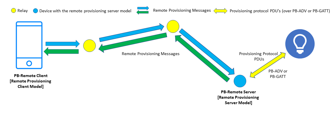
Remote provisioning involves two new models, the Remote Provisioning Client model and the Remote Provisioning Server model. The Remote Provisioning Client model enables provisioner device to communicate with remote unprovisioned device and to control provisioning process. This device is known as the PB-Remote Client. The client model sends and receives provisioning protocol PDUs using model messages. The messages are relayed across the network in the usual way, using managed flooding, directed forwarding, or a combination of the two methods. The Remote Provisioning Server model enables a PB-Remote Client to scan and provision unprovisioned device in its direct radio range. A device implementing this model is called a PB-Remote Server. The server model also supports to execute procedures needed for change of the Device Key or plug-and-play device configuration.
The remote provisioning also defines PB-Remote provisioning bearer. The PB-Remote bearer uses PB-ADV or PB-GATT to communicate with unprovisioned device when implemented on a PB-Remote server device. When implemented on a PB-Remote server device, this bearer enables provisioner to communicate with a remote device participating in the provisioning process.
An interface known as the Node Provisioning Protocol Interface is defined, and this enables a number of important new procedures, including change of the Device Key and plug-and-play device configuration.
The remote provisioning models define messages that:
- Enable the discovery of devices anywhere in the network that are available to be provisioned and in direct radio range of a PB-Remote Server.
- Allow a link to be established between a PB-Remote Server and a selected, unprovisioned node.
- Encapsulate provisioning protocol PDUs, allowing them to be transported between client and server in either direction.
- Are secured with the device key (DevKey) of the node which acts as the server.
- Relate to the Node Provisioning Protocol Interface procedures.
In outline, remote provisioning works by the PB-Remote Server establishing a link to a selected, unprovisioned device at the request of the PB-Remote Client. It then receives provisioning protocol PDUs encapsulated within remote provisioning messages, extracts those PDUs. and sends them over the link, receiving provisioning protocol PDUs in response which it encapsulates within other remote provisioning messages to be sent back to the PB-Remote Client. See Figure 3.
In this way, the PB-Remote Client executes the usual provisioning process with a remote unprovisioned device. The PB-Remote Server acts as an intermediary within the process by translating between bearers and forwarding provisioning PDUs from within PB-Remote messages sent by the client to the unprovisioned device.
Figure 3 – The Architecture of Remote Provisioning
2.2.2 The Stages of Remote Provisioning
Remote provisioning can be thought of as passing through the following four stages:
- Perform remote scanning
- Open a link to the unprovisioned device
- Provision the device
- Close the link
2.2.2.1 Remote Scanning
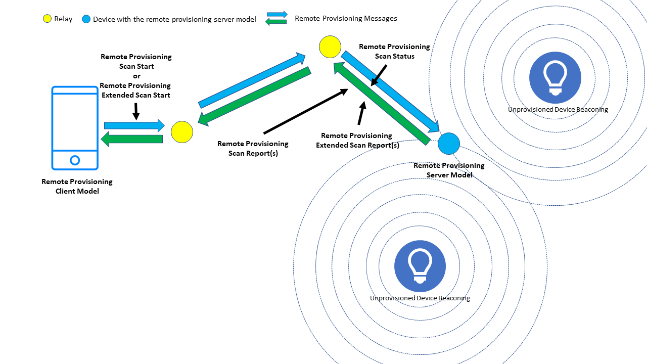
Figure 4 – The Remote Provisioning Scan procedures
Two forms of remote scanning may be requested by a PB-Remote Client, namely Remote Provisioning Scan Start or Remote Provisioning Extended Scan Start. See Figure 4.
2.2.2.1.1 The Remote Provisioning Scan Procedure
A Remote Provisioning Scan Start message is sent to the unicast destination address of a PB-Remote Server, instructing it to commence scanning for devices which are available to be provisioned. The message may include a Device UUID which, if present, indicates that a specific device only is to be scanned for. Alternatively, all unprovisioned devices in range of the PB-Remote Server are to be scanned for. These two options are known as single device scanning and multiple device scanning, respectively.
Remote Provisioning Scan Start is an acknowledged message and a PB-Remote Server node will respond to it with a Remote Provisioning Scan Status message.
Remote Provisioning Scan Report messages are sent by the PB-Remote Server, back to the PB-Remote Client that initiated scanning. These messages contain details of each distinct, discovered unprovisioned device which the server is capable of provisioning and includes information such as the identifying Device UUID, information regarding out of band (OOB) authentication capabilities of the device, the signal strength (RSSI) measured by the PB-Remote Server, and URI Hash value if available from the device being provisioned. Single device scanning will result in a scan report message for the specified Device UUID only (if the device is discovered).
2.2.2.1.2 The Remote Provisioning Extended Scan Procedure
This variant of remote scanning allows the PB-Remote Client to request specific, additional information about a single device which is not to be found within unprovisioned device beacons (in the case of PB-ADV) or in the Service Data AD type of connectable advertising packets (in the case of PB-GATT). Additional information of interest may be available in Bluetooth® LE scan response packets or in additional advertising packets each containing alternate content from the same device.
Extended scanning can obtain information from either a single unprovisioned device or from the PB-Remote Server node itself. In the first of these scenarios, whilst the Remote Provisioning Extended Scan Procedure is performed for a single device only, if the PB-Remote Server implementation supports it, multiple instances of the procedure, each targeting a different Device UUID, may be executed concurrently.
A Remote Provisioning Extended Scan Start message sent by the PB-Remote Client, initiates remote extended scanning by the PB-Remote Server node which has a specified unicast address. It can contain a list of AD types whose values are requested (subject to some limitations documented in the Bluetooth Mesh protocol specification). If a Device UUID is included in the message, scanning for the specified unprovisioned device is performed, otherwise information is acquired from the PB-Remote Server node itself.
Remote Provisioning Extended Scan Start is an unacknowledged message.
Remote Provisioning Extended Scan Report messages are sent by servers back to the PB-Remote Client that initiated extended scanning and contain the information of the requested type(s) that was obtained by the PB-Remote Server.
2.2.2.2 Open a Link
Figure 5 – Opening a remote link to an unprovisioned device
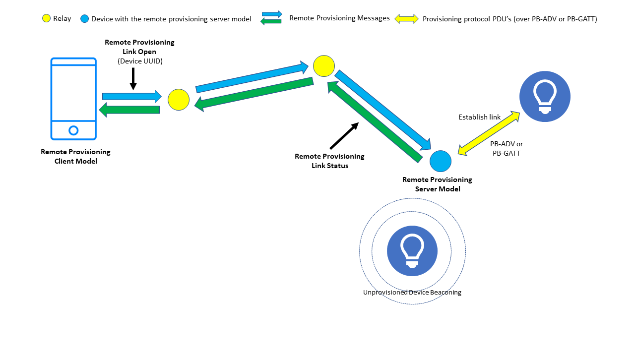
A PB-Remote Client can send a Remote Provisioning Link Open message with a Device UUID parameter to ask the PB-Remote Server node to establish a provisioning link with the specified device. This is an acknowledged message and results in the server sending a Remote Provisioning Link Status message back to the client. See Figure 5.
Note that the Remote Provisioning Link Open message may be used to ready the PB-Remote Server for other procedures, which are available via the new Node Provisioning Protocol Interface (see 2.2.3).
2.2.2.3 Provision the Device
Figure 6 – Remote provisioning
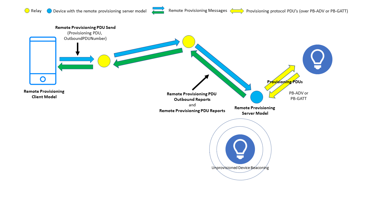
Once a link between the PB-Remote Server node and the target unprovisioned device has been established, the PB-Remote Client may progress the provisioning process itself. The process is essentially the same as the four stages described in 1.1.3.2 to 1.1.3.5 except that the required Provisioning Protocol PDUs are encapsulated within a PB-Remote message type called the Remote Provisioning PDU Send message. The server extracts Provisioning Protocol PDUs from the PB-Remote messages and forwards them over the link to the unprovisioned device. Provisioning Protocol PDUs that are sent by the unprovisioned device to the PB-Remote Server are encapsulated within Remote Provisioning PDU Report messages and sent back to the PB-Remote Client node. See Figure 6.
2.2.2.4 Close the Link
Figure 7 – Closing the remote provisioning link
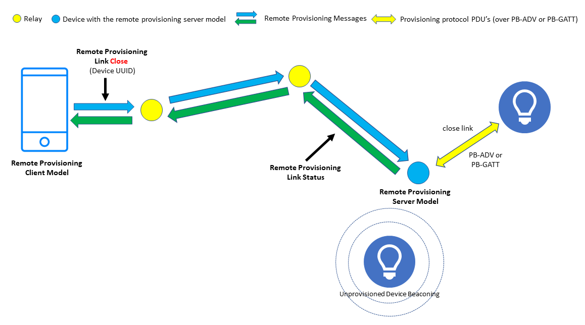
When provisioning has completed, the PB-Remote Client instructs the PB-Remote Server to close its link to the device which was provisioned. This is accomplished by sending a Remote Provisioning Link Close message to which the server responds with a Remote Provisioning Link Status message.
2.2.3 The Node Provisioning Protocol Interface
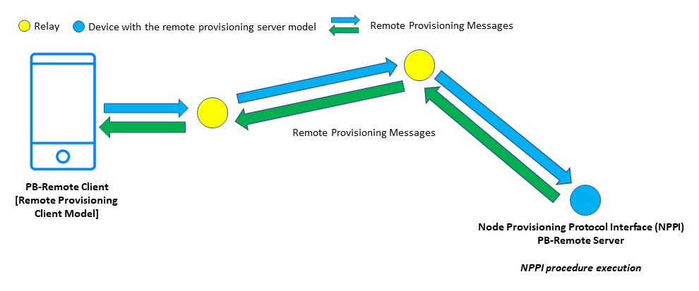
PB-Remote defines a series of procedures which are available via a newly defined interface called the Node Provisioning Protocol Interface (NPPI). A node supporting Remote Provisioning Server model must support the NPPI interface and its associated procedures. Any one of the NPPI procedures may be started by the Remote Provisioning Client model sending a remote provisioning link open message which includes a NPPI Procedure field, indicating the required NPPI procedure. The NPPI procedures are executed by the Remote Provisioning Server model.
The Node Provisioning Protocol Interface is closed until the Remote Provisioning Server model receives a remote provisioning link open message which is addressed to the Remote Provisioning Server model itself. When the interface is open, provisioning protocol PDUs are exchanged per the normal flow (but with some constraints on Provisioning Data PDU values) encapsulated within Remote Provisioning messages. These PDUs are then processed by the Remote Provisioning Server model to execute selected procedures. Note that this is in contrast to the behavior described in 2.2.2.3 where provisioning protocol PDUs are forwarded over a link to an unprovisioned device as shown in figures 5, 6, and 7.
Figure 8 – NPPI architecture
The NPPI procedures defined in the Bluetooth Mesh 1.1 Protocol Specification are as follows.
2.2.3.1 Device Key Refresh
This procedure allows a new device key to be assigned to a node without the need to re-provision the node in full. Existing data such as the node’s element addresses and its lists of NetKeys and AppKeys are unaffected.
The procedure executes over two stages with a new candidate key, called the Device Key Candidate, being computed using the standard provisioning protocol and procedures. This key never leaves the device, and the Diffie-Hellman key agreement protocol, based on elliptic curve cryptography, is used to securely enable the Configuration Manager to possess a copy of it. This ensures that the security associated with this procedure is of the same level as it was during the initial provisioning of a device. At this stage, the node’s device key has not been changed, but a candidate new key value is known to it. In stage 2, the device key candidate becomes the node’s new DevKey when an access message, which was encrypted using the new device key candidate, is received. This indicates that the new key is in use. At this point, the old key is revoked, and the new candidate device key takes its place.
2.2.3.2 Node Address Refresh
The Node Address Refresh procedure allows a node’s unicast address and its device key to be changed without resetting and re-provisioning it. Existing data such as the node’s list of NetKeys and AppKeys are unaffected. It can also be used to change the number of elements that a node has, with each element assigned an address which forms a consecutive range, starting with the new unicast address assigned to the primary element.
2.2.3.3 Node Composition Refresh
This procedure allows a node’s composition (i.e., number of elements and models) to be changed and provides a form of plug-and-play capability to complex devices whose physical compositional structure is dynamic.
Imagine a DALI device in the network. The device is a sophisticated lighting product whose internal bus can accommodate up to 128 different components. Various types of sensors may be plugged into the node or unplugged, for example. Devices of this sort, when programmed with suitable firmware, can detect these types of change.
This NPPI procedure requires a node which has detected a change to its physical composition to write details to Page 128 of the Composition Data state. The procedure, initiated by a PB-Remote Client, ultimately results in the new composition state data being copied from Page 128 to Page 0, where the active composition state data is stored, thus bringing about the required change.
When this procedure is executed, a new device key is also allocated to the node. The Composition Data state of the node is updated by the procedure, but other states are left unchanged.
2.2.4 Remote Provisioning and Security
Figure 9 depicts the way in which remote provisioning is secured. Messages exchanged by the PB-Remote client and server are secured using the device key of the PB-Remote server node. The provisioning procedures which are then executed make use of standard provisioning security, passing through stages 2 – 5 of the usual provisioning procedure as explained in section 1.1.3.
Figure 9 – Remote Provisioning Security
Some of the authentication methods which may be supported by a device rely on the user being able to see, hear, or touch the device. Remote provisioning is designed to allow the provisioning of devices which may be some considerable distance away from the Provisioner, and so authentication methods of these types may not be optimal or may be impractical in some situations. Fortunately, Bluetooth® Mesh version 1.1 also added a new authentication approach which is ideal for out-of-sight, remote provisioning of devices called certificate-based provisioning. This feature is discussed in the Certificate-Based Provisioning Technical Overview Paper.
2.2.5 Bulk Provisioning
Due to the need to be in direct radio range of new devices when provisioning, Bluetooth® Mesh 1.0 did not lend itself to the provisioning of large collections of devices, perhaps all devices in the network without relocating the Provisioner.
Remote provisioning, when combined with certificate-based provisioning, offers the potential for provisioning tools which can be used to programmatically provision every single device in the new network in a single procedure initiated by the commissioner.
3. Close
The Bluetooth® Mesh remote provisioning feature makes the act of provisioning new devices in the network much easier. The new node provisioning protocol interface procedures reflect real-world use cases and ensure the usual workflows involved in establishing a new network and maintaining complex devices are well supported.
Mesh Enhancement
Technical Overviews
Mesh Feature Enhancement Summary
Technical Overviews

