Bluetooth® Mesh networking creates new opportunities for interacting with your environment, whether you’re making your home or office smarter using intelligent lighting, heating/cooling, and security systems, or enhancing the efficiency of an industrial wireless sensor network (IWSN). Bluetooth Mesh networking provides the foundation you need to create truly large-scale device networks, allowing you to enable tens, hundreds, or even thousands of wireless devices to reliably and securely communicate with each other. This article takes a deeper look into the fundamental concepts behind this innovative network topology.
Nodes
Imagine a network made up of thousands of devices, each communicating via Bluetooth® Low Energy (LE) short-burst wireless connections. These devices on a Bluetooth Mesh network are called nodes. Each node sends and receives messages. Information may be relayed from node to node, enabling messages to travel greater distances than radio waves normally allow. This web of nodes (Figure 1) may be spread across manufacturing facilities, office buildings, shopping centers, business campuses, and more.
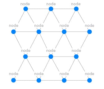
Figure 1 – Nodes in a mesh network
Bluetooth Mesh nodes are diverse and capable of facilitating any number of roles within the mesh network. Light fixtures, machinery, security cameras, smoke detectors, and environmental sensors are just a few examples of roles a node can fulfill.
Elements
Some nodes, such as sensors, run off batteries while other nodes, like light fixtures, manufacturing machinery, and security cameras, draw power from the main grid. Some nodes have more processing power than others. These nodes can take on more complex tasks within the mesh network, assuming different roles and possessing any of the following four node features.
Low-Power Feature: Power constrained nodes may use the low-power feature to reduce radio-on time and conserve power. Low-power nodes (LPNs) work in conjunction with friend nodes.
Friend Feature: Nodes without power constraints are great candidates for being friend nodes. Friend nodes store incoming messages and security updates destined for LPNs; when the LPN requests these messages, the friend node delivers the stored information to the LPN.
Relay Feature: Relay nodes receive and retransmit messages, enabling a larger network as messages are relayed from node to node. Depending on power source and computational ability, a node may take on this feature.
Proxy Feature: Proxy nodes enable transmitting and receiving mesh messages between GATT and Bluetooth Mesh nodes. A node with this role needs a solid power source and computational resources.
Some nodes are more complicated than others and consist of multiple independent parts called elements. Each node has at least one element, known as the primary element, and may have additional elements (Figure 3). Elements are composed of entities that define a nodes’ functionality and the condition of the element. A light bulb, for example, has one element with two functions:
- Node = Light bulb
- One Element = Primary Element
- Functionality of node
-
- On/Off
- Brightness
- Condition/State of Element
-
- On or Off
- 0 – 10 (Brightness Level)
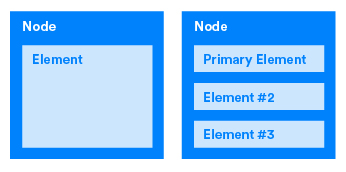
Figure 2 – Nodes must have at least one element and may have multiple elements
Each element within a node has a unique address known as a unicast address, enabling each element to be addressable. We’ll explain addressing in a later part of the Bluetooth® Mesh Networking Series.
Models and States
Whether nodes are networked across a manufacturing floor, hotel, office building, or business campus, a node’s basic functionality is defined and implemented by models. Models reside inside elements, and elements must have one or more models (Figure 3). Models define and implement the functionality and behavior of a node while states define the condition of elements.
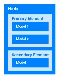
Figure 3 – Node, Element, Model
Using our light bulb example, the model’s functionality is On/Off and Brightness. The associated states are On/Off and 0-10 respectively:
- Model (functionality of node)
- 1. On/Off
- State -> On or Off
- 1. On/Off
-
- 2. Brightness (0-10)
- 2. State -> 0-10
- 2. Brightness (0-10)
Bluetooth® Mesh supports composite states, which are states composed of two or more values. A color changing lamp is an example, as the hue may change independently of color saturation or brightness.
The term bound states is defined as when a change in one state causes a change in another state. A common binding is between level states and On/Off states. If the level changes from 0 to 1 then the On/Off state has also transitioned from off to on.
Every model has a unique identifier. Bluetooth SIG adopted models are 16 bits while vendor models are 32 bits (16-bit Bluetooth assigned company identifier and a 16-bit vendor assigned model identifier). This makes each model uniquely addressable.
Using messages, a Bluetooth Mesh network communicates via a client-server architecture. The function of a server is to expose the states of an element. One of the simplest states is a binary switch where the state is either on or off. A simple server model is the Generic On/Off Server Model, which contains the state representing the switch being either on or off.
Clients access states request, change, or consume the states of a server. An example of a simple client model is a Generic On/Off Client model (binary switch). This Generic On/Off Client Model controls the Generic On/Off Server Model by sending it messages. For example, the client uses this mechanism to turn a light on or off.
This client-server architecture gives rise to three types of models:
- Server Model
- Composed of one or more states spanning over one or more elements.
- Defines messages the model may transmit/receive and defines the element’s behavior given these messages.
- Examples:
- On/Off switch – may expose state of switch
- Sensors – may expose state of sensor (Potentially a value for temperature or full/refill/empty for sensor measuring)
- Power level – may expose state of power (Levels 1-10)
- Client Model
- Defines the set of messages used by the client to request, change or consume corresponding states of a server.
- Examples:
- On/Off switch – Client sends a message of on or off
- Power level – Messages defining the state of power (0-10)
- Control Model
- Control Models have multiple functionality and may contain one or more of the following:
- Client Model(s)
- Server Model(s)
- Control logic (rules and behaviors) coordinating interactions between models it connects with.
- Example: We may use a Control Model for a pump that circulates liquid coolant around a machine.
- Scenario – A temperature sensor records the temperature of a machine. If the machine gets above a defined temperature, the cooling pump turns on.
- Control Module for cooling pump
- A client to the temperature sensor (accepts temperature value)
- A server to the On/Off switch (turns pump on or off)
- Control logic (rules and behaviors) – defines that if temperature sensor is over a defined value, turn pump on.
- Control Models have multiple functionality and may contain one or more of the following:
Model definitions allow you to configure nodes and their functionality within the mesh network. Model definitions, as well as other model concepts, are explored in greater detail in later articles.
Fundamentals Continued
Bluetooth® Mesh networking uses proven, global interoperability and a mature, trusted ecosystem to create industrial-grade device networks. Now that you understand some of the basic concepts behind Bluetooth mesh, check back next week for an overview of other Bluetooth Mesh networking fundamentals, including addressing, publications/subscriptions, messages, lists, and how it all works together to create a Bluetooth Mesh network.
![]()
FEATURED DOWNLOAD
Bluetooth Mesh Models: A Technical Overview
In this detailed technical paper, Martin Woolley provides a guided tour of the Bluetooth Mesh models, taking an in-depth look at building blocks critical to Bluetooth Mesh interoperability.


