Bluetooth® Core 6.0 feature overview
2.2 Decision-Based Advertising Filtering
3.1.1 Device Positioning and Bluetooth LE
3.1.2 Data Transport Architecture
3.2.3 More Information about Channel Sounding
4. Decision-Based Advertising Filtering
4.2 About Decision-Based Advertising Filtering
5.1.5 Bluetooth LE Audio and Acceptor Availability
5.2 About Monitoring Advertisers
6.1.1 Isochronous Communication
6.2 About the ISOAL Enhancement
7.2 About LL Extended Feature Set
| Version: | 1.1 |
| Revision Date: | 15 January, 2025 |
| Author: |
Martin Woolley, Bluetooth SIG |
1. Introduction
Bluetooth® Core Specification 6.0 (Bluetooth® Core 6.0) includes several feature enhancements. This paper provides an overview of each enhancement. Note: This is a marketing document and is not intended to replace or overrule the Bluetooth® Core Specification in any way.
Each feature enhancement is described in a dedicated section and starts with a description of pertinent background information. This is intended to make life easier for those readers that may not have encountered certain aspects of Bluetooth LE before. That said, the background sections are not completely comprehensive and readers who find they are encountering unfamiliar terminology or concepts are encouraged to download and read the Bluetooth LE Primer.
2. At a Glance
2.1 Bluetooth® Channel Sounding
Bluetooth® Channel Sounding enables secure fine ranging between two Bluetooth devices. Ranging means the use of certain techniques to establish a measure of the distance from one object to another.
Wireless ranging has applications in a variety of products, such as digital key solutions and ‘Find My’ networks. The new Bluetooth® Channel Sounding feature has been designed to provide a standards-based technical approach which can meet the challenging accuracy and security requirements that products like this typically have.
2.2 Decision-Based Advertising Filtering
The Bluetooth Extended Advertising feature involves a series of related packets being transmitted on both primary and secondary radio channels.
Decision-based advertising filtering allows a scanning device to use the content of a packet received on a primary advertising channel to decide whether to then scan for related packets on the secondary channels. This improves scanning efficiency by reducing the time spent scanning on secondary channels for packets which might not contain PDUs that are relevant to the application.
2.3 Monitoring Advertisers
The host component of an observer device may instruct the Bluetooth LE controller to filter duplicate advertising packets. When filtering of this type is active, the host will only receive a single advertising packet from each unique device (subject to core specification definitions of what constitutes a unique device in this context). This improves efficiency for the host but has the disadvantage that the host has no way of knowing whether a device is still within range when circumstances dictate that the observer device should now attempt to connect to it. This can lead to the observer wasting energy performing high duty cycle scanning for a previously discovered device that is no longer in range.
The new Monitoring Advertisers feature uses Host Controller Interface (HCI) events to inform the host whenever a device of interest moves in and out of range.
2.4 ISOAL Enhancement
The Isochronous Adaptation Layer (ISOAL) makes it possible for larger data frames to be transmitted in smaller link layer packets and ensures the associated timing information that is needed for the correct processing of the data by receivers can be reconstituted.
ISOAL can produce either framed or unframed PDUs depending on certain variables. If framed PDUs are produced latency can be increased as a result.
In Bluetooth® Core 6.0, ISOAL has been improved by defining a new framing mode that reduces latency for use cases that are particularly sensitive to this issue. The same feature also improves reliability.
2.5 LL Extended Feature Set
Devices are able to exchange information about the link layer features that they each support. This capability has been enhanced to support larger numbers of features, having become necessary as the sophistication and versatility of Bluetooth LE has grown.
2.6 Frame Space Update
Prior versions of the Bluetooth® Core Specification define a constant value for the time that separates adjacent transmissions of packets in a connection event or connected isochronous stream (CIS) subevent. The value is designated T_IFS in the specification and had a fixed value of 150 µs.
In Bluetooth® Core 6.0 of the core specification, frame spacing, as used in connections or with connected isochronous streams is now negotiable and may be either shorter or longer than 150 µs.
3. Bluetooth® Channel Sounding
3.1 Background
This section provides an overview of aspects of Bluetooth LE technology, which helps better understand and appreciate the new Bluetooth® Channel Sounding feature.
3.1.1 Device Positioning and Bluetooth LE
Since Bluetooth LE was first specified in the Bluetooth Core Specification, core features such as Direction Finding and a number of associated profiles such as the Find Me profile have established Bluetooth LE as a popular technology for location services.
 Figure 1 – Direction Finding using AoA and AoD
In addition, several proprietary beaconing message formats that are transmitted within standard Bluetooth LE advertising packets have been widely adopted.
Many applications require the distance between two Bluetooth devices to be calculated. Prior to the release of Bluetooth Core Specification version 6.0, this could only be accomplished using a method known as a path loss calculation. This method requires the receiving device to measure the received signal strength (referred to as the RSSI) and to know the strength of the signal transmitted by the remote device at some reference distance from the transmitter such as 1 meter. In addition, the relevant physics indicates that the signal strength at a receiver is inversely proportional to the square of its distance from the transmitter. Armed with the transmitter reference signal strength, the RSSI and this simple mathematical relationship it is possible to calculate a distance value.
 Figure 2 – Inverse square path loss over distance
Path loss calculations are suitable when the required accuracy of the distance calculation, and the consistency and reliability of such calculations is not particularly high. Due to the way the signal strength initially drops off quickly (see Figure 2) when the distance between two devices is relatively small, path loss calculations can yield reasonably good results. But over longer distances, a small signal strength variation can correspond to a large possible range of distances, making the calculation very sensitive to small errors. The method is vulnerable to interference and the impact of other environmental factors. It is also insecure, leaving applications at risk of attacks such as distance spoofing, for example.
The more challenging requirements of applications such as asset tracking and keyless entry and ignition systems require a more sophisticated, secure, and standardized approach which can yield more accurate and more reliable results.
3.1.2 Data Transport Architecture
The Bluetooth Core Specification defines several concepts that collectively constitute the Bluetooth data transport architecture. Among these concepts are the Physical Transport, Physical Channel, Physical Link, Logical Link, and Logical Transport. Certain combinations and configurations are defined for use in support of different application types, each with particular characteristics relating to properties such as topology, timing, reliability, power, and channel use. The terms operational mode or mode of operation are sometimes used informally to refer to the various data transport architecture configurations.
 Figure 3 – Part of the Bluetooth data transport architecture
Figure 3 shows a small part of the data transport architecture, highlighting two of the most commonly used logical transports and their associated physical link, physical channel and physical transport components. Both of these logical transports have relevance to Bluetooth® Channel Sounding.
3.1.2.1 LE-ACL
LE-ACL is one of the most commonly used Bluetooth LE logical transport types, providing for connection-oriented communication of data between two devices. In fact, ACL connections are generally referred to simply as connections.
The device that requests a connection is called the Central. The device that receives and grants this request is called the Peripheral.
When two devices establish an ACL connection, they agree on a number of timing parameters that govern their subsequent communication. Key amongst these parameters is the connection interval. The connection interval parameter defines how often in milliseconds, the radio can be used for servicing this connection.
ACL connections may be encrypted in which case all payloads are encrypted by the link layer before packet transmission occurs and are decrypted when received by the peer device’s link layer.
3.1.2.2 ADVB
ADVB is the Advertising Broadcast logical transport. It provides a connectionless communication mode and may be used to transfer data to one or more devices concurrently or to indicate the presence of a Peripheral device, allowing other devices to discover it.
3.2 About Bluetooth® Channel Sounding
3.2.1 Overview
The Bluetooth® Channel Sounding feature of Bluetooth LE consists of two distinct methods of distance measurement which may be used independently or in combination. The two methods are called Phase-Based Ranging (PBR) and Round-Trip Timing (RTT).
The system supports the calculation of significantly more accurate distance measurements than the path loss method, is less vulnerable to interference and the impact of environmental factors and incorporates numerous security mechanisms.
This section provides an introduction to Bluetooth® Channel Sounding. For a more in-depth and comprehensive explanation, see the associated paper Secure Fine Ranging with Bluetooth® Channel Sounding, which is available from the Bluetooth SIG website, https://www.bluetooth.com.
3.2.2 Technical Highlights
3.2.2.1 System Architecture
Bluetooth® Channel Sounding takes place between two connected devices in a 1:1 topology. The device that wishes to calculate the distance from itself to another device is called the Initiator. The other device is called the Reflector.
During channel sounding multiple bidirectional exchanges take place between the Initiator and Reflector during pre-agreed time slots.
In the Bluetooth stack, channel sounding is primarily a function of the Bluetooth controller as opposed to the host part of the stack. The Initiator’s controller passes low-level measurements up to the host and ultimately, to the application layer using the Host Controller Interface (HCI). It is the application’s responsibility to use the channel sounding data provided by the controller to calculate distance measurements.
 Figure 4 – CS device roles and host/controller function distribution
Devices that use Bluetooth® Channel Sounding may include an antenna array. This can improve the accuracy of distance measurements by offering a series of different communication paths and lessening the impact of multi-path propagation.
3.2.2.2 Bluetooth® Channel Sounding and the Data Transport Architecture
Figure 5 depicts a subset of the full data transport architecture and shows the new physical link and physical channel types which have been added to support channel sounding.
 Figure 5 – CS and the Data Transport Architecture
Channel sounding is initiated using an ACL connection between the two devices. Once channel sounding has been started, the ACL connection continues to act as a transport for link layer control exchanges and to provide a timing reference for the channel sounding radio activity scheduling. Channel sounding uses the new Channel Sounding Physical Link and the Channel Sounding Physical Channel.
The Initiator and Reflector roles may each be assumed by either the Central or the Peripheral device.
3.2.2.3 Distance Measurement Methods
3.2.2.3.1 Phase-Based Ranging (PBR)
The PBR method exploits a fundamental property of radio signals known as phase and its relationship with frequency and wavelength. Phase can be thought of as a fraction of a wave cycle and is generally expressed as an angle between 0 and 2π radians. Changes in phase are sometimes attributed to phase rotations.
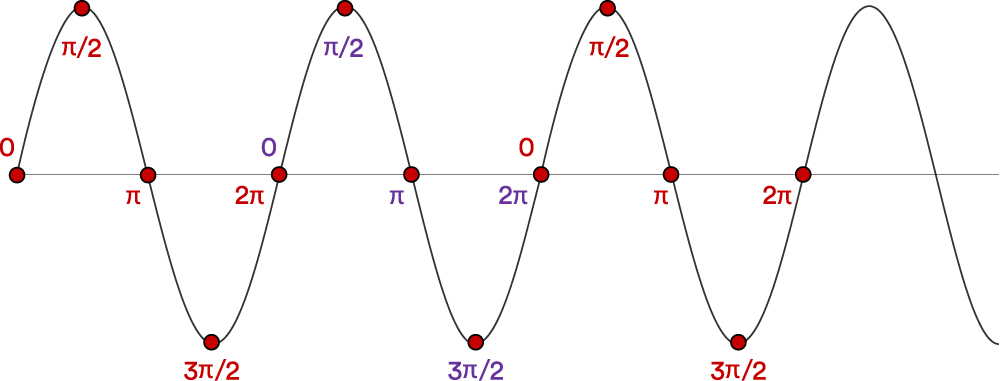 Figure 6 – Phase value examples within several wave cycles
Figure 6 shows example phase values corresponding to points within a radio signal. Note the cyclic, repeating nature of the values across multiple wave cycles.
When using PBR, the Initiator transmits a signal at a given frequency, f1 to the Reflector. The Reflector transmits a signal back to the Initiator which on receiving the reply, measures the phase of the received signal which we will refer to here as Pf1.
 Figure 7 – Initiator sends a channel sounding signal which the Reflector echoes
Next, the Initiator transmits another radio signal, this time with a different frequency, f2. The Reflector echoes the received signal back to the Initiator once again. Changing the frequency changes the wavelength and consequently the phase Pf2 measured by the Initiator on receiving the response from the Reflector will also change.
The Initiator may now calculate the distance between the two devices using a formula that involves the frequency difference (f1 – f2), the phase difference (Pf1 – Pf2) and the speed of light.
In practice, devices will typically exchange more than two signals at more than two different frequencies as the availability of more low-level measurements can improve the accuracy of the distance measurements calculated by the application.
The phase value as measured by the Initiator changes as the distance between the devices increases but at a certain point will reset to zero and phase values will start to repeat. This is due to the cyclic nature of phase rotations, as shown in Figure 6. In the context of distance measurement, this phenomena is known as distance ambiguity since the same phase value can be encountered at multiple different distances. Exactly when distance ambiguity is first encountered depends on the difference between the frequencies of the channel sounding signals. This difference value is known as the frequency separation. In general, distance ambiguity occurs earlier, the larger the frequency separation. Bluetooth CS uses a frequency separation of 1 MHz and distance ambiguity does not arise until around 150 meters.
The problem of distance ambiguity can be addressed by using PBR in conjunction with the second distance measurement method, Round-Trip Timing.
3.2.2.3.2 Round-Trip Timing (RTT)
The RTT method involves the Initiator transmitting a packet to the Reflector and the Reflector sending the same packet back. In this and only in this respect is there any similarity with the PBR method.
To enable the calculation of a distance measurement, the Initiator records a timestamp when transmitting its packet. This time is known as the Time of Departure or ToD. On receiving the reply packet from the Reflector, it records a timestamp again with this time known as the Time of Arrival or ToA.
If we refer to the time that elapses between ToD and ToA as TA-D then a measure of the distance traveled could be obtained by multiplying TA-D by the speed of light (c) and then (since this is a bidirectional round-trip time), dividing by 2. This yields a very crude estimate of distance however since it does not take into account the time taken for the Reflector to receive the packet, process it, formulate the response and transmit it. This processing requires what might seem like a short and inconsequential period of time but a radio transmission, travelling at the speed of light (in a vacuum) can travel 300 meters in a microsecond and so very small inaccuracies in the calculation of the time of flight can have a very substantial impact on the calculated distance. Accurately determining the time that radio signals actually spend in-flight is therefore key to obtaining accurate distance measurements with the RTT method.
RTT in Bluetooth® Channel Sounding ensures that the time it takes the Reflector to turn around the received CS packet and send it back to the Initiator is known and this time value can therefore be used in calculations to produce a more accurate time of flight.
The Bluetooth Core Specification defines several different methods for capturing ToA and ToD timestamps. The choices of method vary in complexity and in their accuracy. The most accurate time capture methods are known as fractional timing estimates. Capturing ToA and ToD values as accurately as possible will yield the most accurate distance measurements.
3.2.2.4 Channel Sounding Initialization
Before channel sounding can commence, the Initiator and Reflector must have established an encrypted ACL connection. This connection is then used for the secure exchange of link layer control PDUs associated with channel sounding initialization procedures.
Bluetooth® Channel Sounding has its own distinct security features. The first channel sounding procedure to be executed is the CS Security Start procedure. This procedure equips both devices with initialization vector (IV), instantiation nonce (IN) and personalization vector (PV) values which are subsequently used during channel sounding as inputs to a new security function, the Deterministic Random Bit Generator (DRBG). DRBG is used in many of the channel sounding security features (see 3.2.2.10 Bluetooth® Channel Sounding Security Overview). The security of the encrypted ACL connection protects the exchange of this important data.
The Bluetooth® Channel Sounding feature affords developers a range of options with which to control or influence the distance measurement methods used, the accuracy of measurements, latency resultant from the procedure, security and other variables. Devices will not necessarily have identical channel sounding abilities and the CS Capabilities Exchange procedure allows the two devices to swap information about capabilities and preferences.
Having exchanged capabilities data, the devices participate in the CS Configuration procedure and agree the configuration parameters that will govern the channel sounding procedure when it starts.
When using the PBR method, the Reflector is expected to echo back signals received from the Initiator at the same frequency. But all devices can exhibit some degree of inaccuracy in the frequency of generated signals, where the intended or wanted frequency differs from the actual, measured frequency of the generated signal. Frequency is directly related to wavelength and the PBR method relies on this relationship. Inaccuracies in the frequency of echoed signals from the Reflector can impact the accuracy of distance measurements, therefore. Consequently, devices may be equipped by the manufacturer with a table of data called the Fractional Frequency Offset Actuation Error (FAE) table which for a collection of reference frequencies, provides a measure of the difference between the frequency of a generated signal and the expected or requested frequency, expressed in Parts Per Million (ppm). Using the Mode-0[1] FAE Table Request procedure, the Initiator can request the FAE table from the Reflector and can take this data into account when performing its calculations.
Having completed the initialization procedures, channel sounding may then start. This involves the two devices making a series of exchanges of various types for the purpose of taking measurements that can be used by an application for distance calculations.
3.2.2.5 Time Division
Channel sounding involves the use of the Channel Sounding Physical Channel from the general Bluetooth data transport architecture (see 3.2.2.2 Channel Sounding and the Data Transport Architecture). This defines how time is subdivided and used for RF activity.
3.2.2.5.1 Events, Subevents and Steps
Channel sounding takes place in a series of procedures. Each procedure consists of a number of events and each event is further partitioned into subevents. The final subdivision of time within this hierarchical scheme is the step. It is within steps that RF exchanges between Initiator and Reflector takes place.
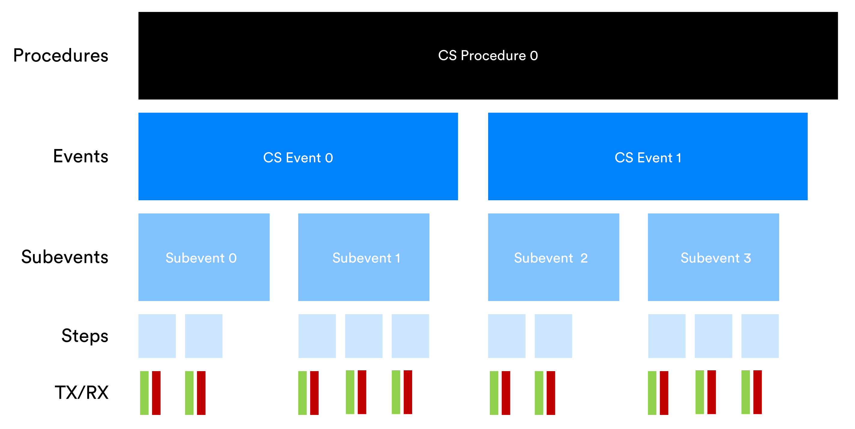 Figure 8 – Structure of Channel Sounding procedures in an example configuration
Various configuration parameters control aspects of this structure including the cardinality of the relationship between elements at different levels (e.g. the number of steps per subevent), the duration of events and what activity takes place in steps. For example, there are always at least 2 steps and a maximum of 160 steps in a subevent. There are a maximum of 256 steps per procedure.
3.2.2.5.2 Timing Anchor Point
All channel sounding procedure, event, subevent and step start times are directly or indirectly anchored to a selected connection event in the associated LE ACL connection over which the link layer procedures to initiate channel sounding were executed.
3.2.2.6 Bluetooth® Channel Sounding Steps
3.2.2.6.1 Packets and Tones
During a CS Step, devices exchange a series of packets known as CS Sync packets and optionally, tones known as CS Tones.
CS Sync packets can be transmitted using either the LE 1M or LE 2M PHY. The GFSK[2] modulation scheme is used in either case, as with other Bluetooth LE packets.
A CS Tone is a signal that uses Amplitude Shift Keying (ASK) to create a symbol whose frequency is fixed.
Steps have an associated mode which is numbered from 0 to 3 inclusive. The mode defines details of the exchange to take place in the step and its purpose.
- A mode-0 step is concerned with calibration and allows the Initiator to determine the extent to which the Reflector’s generation of a given frequency might differ from its own. This yields a value called the Fractional Frequency Offset (FFO) which is used in calculations to compensate for frequency generation differences. Mode-0 steps involve the exchange of CS Sync packets.
- A mode-1 step uses CS Sync packets in the application of the round-trip timing (RTT) method.
- A mode-2 step involves the exchange of CS Tones for the purpose of Phase-Based Ranging (PBR).
- A mode-3 step exchanges both CS Sync packets and CS Tones and allows data for both the RTT and PBR methods to be collected in a single step. Support for mode-3 is optional.
Which step modes are used in a channel sounding procedure depends on rules in the Bluetooth Core Specification and the configuration agreed by the two devices. This includes which distance measurement method or methods to use i.e. RTT and/or PBR.
3.2.2.6.2 Mode Combinations and Sequencing
Bluetooth® Channel Sounding allows step modes to be combined and sequenced in various patterns within a procedure, with the application layer given much control which it exercises during configuration. The application layer can also configure the number of repetitions of a channel sounding procedure to be performed and other variables that impact the number of packets or tones exchanged and in some respects, their content.
Applications will consider issues such as the required accuracy of distance measurement, latency tolerance and security needs when determining the optimal configuration to seek to establish. For example, a larger number of exchanges will in general provide more measurements and may help improve accuracy but at the expense of increased latency.
There are always at least two different step modes involved in each subevent. Mode-0 always starts every subevent and one or two other modes may be used for other steps in the same subevent, subject to certain permitted combinations that are presented in the Bluetooth Core Specification and repeated here in Table 1.
|
Main_Mode |
Sub_Mode |
|---|---|
|
Mode-1 |
None |
|
Mode-2 |
None |
|
Mode-3 |
None |
|
Mode-2 |
Mode-1 |
|
Mode-2 |
Mode-3 |
|
Mode-3 |
Mode-2 |
Table 1 – Permitted non-mode-0 mode combinations.
Table 1 also introduces the terms Main_Mode and Sub_Mode. These terms relate to the way in which repeating patterns of step modes can be created via a number of configuration parameters. The configuration procedure will result in one of the modes 1 – 3 being designated the main mode and optionally, another being the sub mode.
In general, step mode sequencing follows this pattern:
- One or more mode-0 steps start the subevent.
- A sequence of n main mode steps then follows, where n is randomly selected and falls within a configured range.
- A single sub mode step follows the sequence of n main mode steps in accordance with a process that the Bluetooth Core Specification calls sub_mode insertion.
Step mode sequences are not tied to subevent boundaries other than by the general rule that subevents must always start with one or more mode-0 steps. Full sequences can span more than one subevent.
3.2.2.7 RF Channels
3.2.2.7.1 Channels and Channel Filtering
For the purposes of channel sounding, 72 channels are defined, each with a 1 MHz width and a unique channel index value. The arrangement of these channels ensures that the LE primary advertising channels are avoided.
A channel width of 1 MHz rather than the usual 2 MHz ensures that the frequency separation between PBR signals that use adjacent channels is such that distance ambiguity does not arise until around 150 meters.
A special channel map called the CS Channel Map indicates which channels to include in channel selection and which to avoid. A link layer control procedure allows Initiator and Reflector to provide updates to this table based on local RF conditions.
Frequency hopping involves the selection of a new channel from those that are marked as available. This usually takes place just before the execution of each step except where a mode sequencing feature called Main Mode Repetition is in use.
3.2.2.7.2 Channel Selection
A new set of three channel selection algorithms (CSA) has been defined for use in Channel Sounding. Collectively they are known as CSA #3 and individually as CSA #3a, CSA #3b and CSA #3c.
CSA #3a is used solely for selecting the channel to use in mode-0 steps.
CSA #3b and CSA #3c are both designed for use with non-mode-0 steps but only one of the two may be used during a channel sounding procedure instance.
Two channel lists are maintained during channel sounding. The first is used only with CSA #3a and the selection of channels for mode-0 steps. The second is used for non-mode-0 steps with CSA #3b or CSA #3c.
CSA #3a and CSA #3b work in an identical way but act upon different channel lists. Each use the same algorithm which randomizes the order of channels marked as included to create a shuffled channel list. Each entry in a shuffled channel list is unique and used only once. When all entries in the shuffled channel list have been used it is regenerated, creating a new randomized list of channels.
Algorithm CSA #3c is significantly different to CSA #3b. Subsets of the included channels in the channel map are organized into groups and channel patterns within the groups which form shapes are generated. Two pattern types are supported and named hat and X. CSA #3c may offer some advantages in detecting reflected signal paths in some circumstances. Consult the Bluetooth Core Specification for further details. Support for CSA #3c is optional.
3.2.2.8 The LE 2M 2BT PHY
The physical layer of Bluetooth LE includes the definition of several permitted configurations known as PHYs. The definition of a PHY includes the modulation scheme used and its parameters such as symbol rate, minimum frequency deviation and Bandwidth-Bit Period Product (BT).
Prior to version 6.0 of the Bluetooth Core Specification, there were three defined PHYs. Their names are LE 1M, LE 2M and LE Coded. The LE Coded PHY is identical to the LE 1M except that packets are subject to additional coding which enables error detection and correction.
A new physical layer configuration called LE 2M 2BT has been introduced in version 6.0. This new PHY may only be used with Bluetooth® Channel Sounding.
A comparison of the four PHYs appears in Table 2.
|
|
LE 1M |
LE Coded |
LE 2M |
LE 2M 2BT |
|---|---|---|---|---|
|
Symbol Rate |
1 Msym/s |
1 Msym/s |
2 Msym/s |
2 Msym/s |
|
BT |
0.5 |
0.5 |
0.5 |
2.0 |
|
Min. Frequency Deviation |
185 kHz |
185 kHz |
370 kHz |
420 kHz |
|
Error Detection |
CRC |
CRC |
CRC |
N/A |
|
Error Correction |
NONE |
FEC |
NONE |
N/A |
|
Requirement |
Mandatory |
Optional |
Optional |
Optional. Only to be used with Channel Sounding. |
Table 2 – Comparison of PHYs
The Bandwidth-Bit Period Product (BT) is an attribute of a signal that provides information about the relationship between its bandwidth and the duration of symbols.
BT affects the shape and span of the radio pulses that constitute symbols. A higher BT value results in a narrower, squarer pulse and a lower value results in a wider, more rounded pulse shape.
A BT value of 2.0 improves the security of channel sounding with respect to certain types of physical layer attack. See 3.2.2.10 Bluetooth® Channel Sounding Security Overview.
3.2.2.9 SNR Control for Channel Sounding Steps
Some radio transmitters have the ability to adjust their signal-to-noise ratio (SNR) to lie within a specified range. The SNR Control feature allows the Initiator and Reflector device to agree a SNR output level to use during CS mode-1 and mode-3 steps for CS Sync packet transmission. Adjusting the SNR involves artificially mixing a degree of noise into the signal. The presence of this noise is not an issue for the two CS devices since the output SNR is known to both devices. The risk of some types of physical layer main-in-the-middle attacks is reduced by this technique.
3.2.2.10 Bluetooth® Channel Sounding Security Overview
Security issues that are unique to distance measurement solutions generally involve the threat of untrusted devices somehow tricking one trusted device into concluding that another trusted device is sufficiently close for some action to be granted or taken. For example, in a keyless entry system, if a malicious device could fool the door lock into thinking the associated trusted wireless key card was sufficiently close for the door to be automatically unlocked, an unauthorized party could gain entry.
A series of attacks concerned with distance measurement are recognized by security experts. Some involve stand-alone malicious devices faking communication from a trusted device (known as spoofing) and others are types of man-in-the-middle (MITM) attacks which relay signals from trusted devices, typically manipulating the signal or its digital content in the process to cause the trusted device to miscalculate the distance from it to its trusted counterpart. The details of such attacks vary in sophistication and in the complexity and cost to implement.
Bluetooth® Channel Sounding includes a collection of features which can act as countermeasures to a number of distance measurement security threats. These features can be regarded as falling into four categories:
- Using PBR and RTT methods in combination.
- Calculating distances using data from both the PBR and RTT methods allows the values to be cross-checked. A significant difference should be treated with suspicion by the application. Attacks that target both methods and produce compatible, sufficiently similar results to avoid detection by cross-checking are regarded as highly complex and costly to implement.
- Randomization of the bit stream and transmission patterns.
- Random bit values are transmitted in randomly selected positions in the bit stream. Values and positions are generated or selected using the new Deterministic Random Bit Generator (DRBG). Initiator and Reflector both possess the same IN, IV and PV values (see 3.2.2.4 Bluetooth® Channel Sounding Initialization) and consequently their respective instances of DRBG produce the same stream of randomly generated bits when invoked. This means the two legitimate devices know what random bit values to expect and where to find them. Malicious devices are not in possession of the IN, IV and PV values and so can only guess these values. The probability of guessing all random parts of the bit stream in every exchange is very low. In addition, some time slots are used or not used for transmission at random, once again controlled by DRBG and predictable only by the legitimate CS devices.
- Defense against symbol manipulation
- Certain MITM attacks involve manipulating radio symbols so that the target device incorrectly calculates the distance to the other legitimate device. Such attacks rely on transmissions being found by the attacker in a fraction of a microsecond from amongst the range of potential RF channels and the symbol then rapidly manipulated.
- The addition of noise to transmissions when using the SNR Control feature, adds to the processing time which an attacker must expend in signal analysis. If enough extra processing time is required, the attack is rendered ineffective.
- The LE 2M 2BT PHY has a shorter symbol span which makes symbols harder to intercept and manipulate in this way.
- RF signal analysis techniques including attack detection.
- The Bluetooth Core Specification includes a description of an attack detector system for Bluetooth® Channel Sounding. This includes a standardized metric for reporting the probability of an attack being underway to the application layer. This metric is called the Normalized Attack Detector Metric or NADM. A NADM value is assigned by the controller based on evaluation of the received signal and takes the form of a sliding scale that indicates attack likelihood in a range that starts with attack is extremely unlikely and increases to attack is extremely likely at the uppermost bound. Table 3 contains the NADM value definitions, reproduced from the Bluetooth Core Specification.
| NADM Value | Description |
|
0x00 |
Attack is extremely unlikely |
|
0x01 |
Attack is very unlikely |
|
0x02 |
Attack is unlikely |
|
0x03 |
Attack is possible |
|
0x04 |
Attack is likely |
|
0x05 |
Attack is very likely |
|
0x06 |
Attack is extremely likely |
|
0xFF |
Unknown NADM. Default value for RTT types that do not have a random sequence or sounding sequence. |
Table 3 – NADM values
In addition, Bluetooth controller implementers and application developers may augment the standard security features provided by the Bluetooth® Channel Sounding security features with additional safeguards if required.
3.2.3 More Information about Bluetooth® Channel Sounding
For a more extensive review of the Bluetooth® Channel Sounding feature, a paper dedicated to the topic has been prepared by the Bluetooth SIG. It is titled Secure Fine Ranging with Bluetooth® Channel Sounding and is available for download from the Bluetooth SIG website.
The Bluetooth Core Specification is the sole reference for implementors.
4. Decision-Based Advertising Filtering
4.1 Background
This section explains aspects of Bluetooth LE technology that are relevant to the decision-based advertising filtering (DBAF) feature.
4.1.1 Link Layer States
The Link Layer is one of the most sophisticated parts of the Bluetooth LE stack. It defines packets and PDUs for transmission over the air, as well as patterns of transmitter and receiver behaviors that are part of the definition of the various logical transports.
A device possesses one or more instances of the link layer and each instance is in a particular state at a given time. States and permitted transitions between them are defined by the link layer state machine.
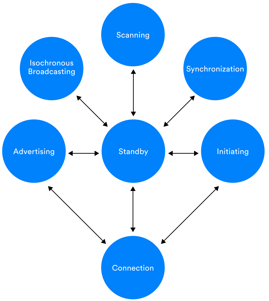 Figure 9 – The Link Layer State Machine
Table 4 provides a short description of each link layer state.
|
State |
Description |
|---|---|
|
Standby |
Device neither transmits nor receives packets. |
|
Initiating |
Responds to advertising packets from a particular device to request a connection. |
|
Advertising |
Transmits advertising packets and potentially processes packets sent in response to advertising packets by other devices. |
|
Connection |
In a connection with another device. |
|
Scanning |
Listening for advertising packets from other devices. |
|
Isochronous Broadcast |
Broadcasts isochronous data packets. |
|
Synchronization |
Listens for periodic advertising belonging to a specific advertising train transmitted by a particular device. |
Table 4 – Link Layer State Descriptions
The advertising, scanning and initiating states are of relevance to the DBAF feature.
4.1.2 Filter Policies
A filter policy defines criteria by which the link layer will decide whether to accept received packets and pass them onto the next stage of processing. A number of filter policies are defined for use in different states. Filter policies can be selected and configured by the host using HCI commands.
The filter policies used in the scanning and initiator link layer states are of relevance to DBAF.
When in the scanning state, a scanning filter policy is applied by the link layer instance to advertising packets that are received. Prior to the addition of the DBAF feature, two basic scanning filter policies were defined. The unfiltered scanning filter policy results in all received advertising packets being accepted. When using the filtered scanning filter policy, only those advertising packets from devices that are identified in a filter accept list (which is populated by the host) are accepted. An extended scanning filter policy is defined for use with directed advertising where PDUs include the address of the target device to which the advertising packet is addressed.
An initiator filter policy is similar to a scanning filter policy but is intended to select those connectable advertising PDUs[3] to which a connection request might be sent in reply. Prior to DBAF, two initiator filter policies were defined. In the first case, only connectable advertising packets from a specific device are selected. In the second, connectable advertising packets from all devices that are members of the filter accept list are accepted.
In all cases, the application of a filter policy results in a decision taken by the link layer either to accept a received packet or to discard it.
4.1.3 Extended Advertising
Several forms of advertising are defined by the Bluetooth Core Specification. The Advertising Broadcast (ADVB) logical transport involves the transmission of advertising packets to a slightly randomized timing schedule. ADVB has a basic form known as legacy advertising and a more sophisticated variant known as extended advertising.
Legacy advertising involves the transmission of packets on only the three primary advertising channels, which have channel index values of 37, 38 and 39 and does not involve the other, secondary advertising channels.
Extended advertising uses all 40 of the Bluetooth LE RF channels. Header data is transmitted on the primary channels in a PDU type known as the ADV_EXT_IND PDU. This PDU type does not include the AdvData field and as such, carries no application data payload. Instead, it often includes a field called AuxPtr that references an associated auxiliary packet containing an AUX_ADV_IND PDU and which is transmitted on one of the 37 secondary advertising channels. It is this PDU that contains the AdvData payload field.
AuxPtr includes a channel index value, indicating the channel that the auxiliary packet will be transmitted on, the used PHY, and a timing offset so that receivers know when, where, and how to receive it. Packets transmitted on a secondary channel and referenced by the AuxPtr field from a packet on the primary channels are known as auxiliary packets, while the referencing packet is known as a superior packet.
Larger application data payloads may be fragmented and sent as series of linked PDUs. The series starts with an AUX_ADV_IND PDU and continues with a number of AUX_CHAIN_IND PDUs. The AUX_ADV_IND PDU and each successive AUX_CHAIN_IND PDU are linked using the AuxPtr field. Figure 10 shows an example of extended advertising which features PDU chaining.
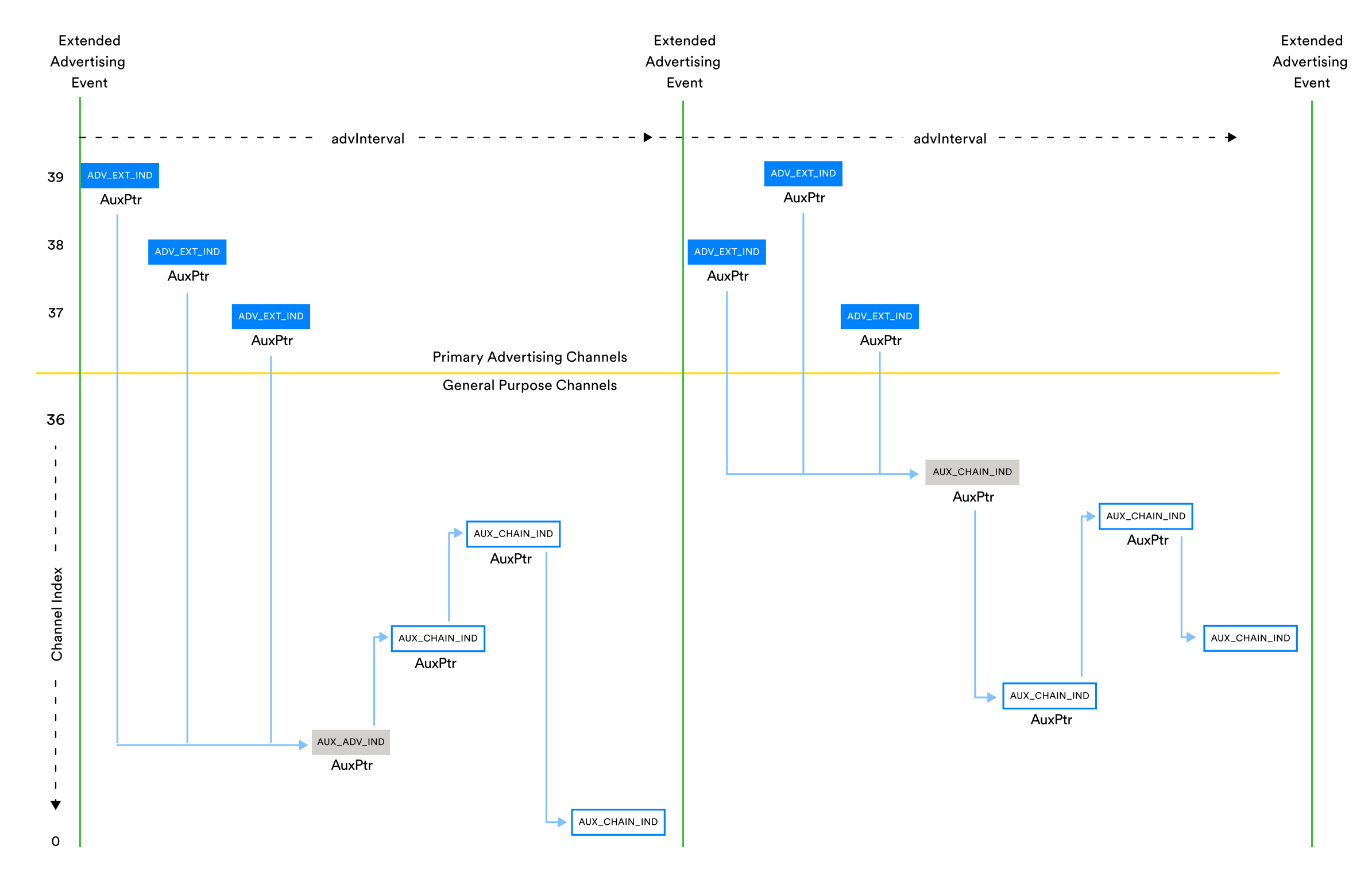 Figure 10 – Extended Advertising with PDU chaining
Extended advertising PDUs such as ADV_EXT_IND include an Extended Header. This contains a series of fields whose presence in the PDU is mandatory, optional or conditional depending on rules that are stated in the Bluetooth Core Specification.
4.1.4 The Initiating State
In the initiating state, a device seeks to transition from the scanning state to the connection state. It does so my listening for a connectable advertising PDU from the target device and having received one, replying with a CONNECT_IND PDU (legacy advertising) or an AUX_CONNECT_REQ PDU (extended advertising).
4.1.5 Issues
DBAF improves the effective duty cycle of scanning devices in situations that may arise where extended advertising is in use. It does this by addressing an issue known as distractions.
4.1.5.2 Distractions
4.1.5.2.1 What is a Distraction?
ADV_EXT_IND PDUs, transmitted on the primary channels contain no application layer data. In certain cases, the Observer (the scanning device) must follow AuxPtr, receive the associated auxiliary PDU on the secondary channel and examine the contents of the AdvData payload field before it can decide whether or not the advertised data is of interest. To do so, it must stop scanning on the primary channels and switch to scanning on the secondary channel indicated in the AuxPtr field.
Depending on the scenario, it may be that much of the time it will turn out that the advertised data is of no interest. This is an issue because during the time that the Observer was scanning on the secondary channel indicated by AuxPtr, it was no longer scanning on the primary channels and consequently, may have missed packets that were relevant.
This situation, where following AuxPtr to scan for and receive a packet that is of no interest to the application layer is known as a distraction.
Distractions reduce the effective duty cycle of the Observer. Missing packets on the primary channels as a result of being distracted can reduce the overall data transfer rate experienced by devices that use extended advertising as a connectionless data transfer mechanism and can increase latency in others.
4.1.5.2.2 Advertising Sets and Duplicate Data
The extended header field of extended advertising PDUs includes an optional field called AdvDataInfo (ADI). ADI contains two sub-fields, Advertising Data ID (DID) and Advertising Set ID (SID). SID identifies an advertising set which a transmitted PDU belongs to. DID contains a random number which changes only when a PDU transmitted by the same advertising device and which is a member of the same advertising set contains new data.
AdvDataInfo can be included in ADV_EXT_IND PDUs transmitted on the primary channel and which have an auxiliary packet associated with them. This affords scanning devices the opportunity to select only PDUs belonging to the relevant advertising set and to recognise duplicate data which they have already received. When either of these conditions apply, the Observer can avoid the need to scan for the auxiliary packet on the secondary channels.
The AdvDataInfo field helps avoid wasted scanning on secondary channels but is an insufficiently sophisticated mechanism for some scenarios.
4.2 About Decision-Based Advertising Filtering
4.2.1 Overview
DBAF introduces a new type of extended advertising PDU called ADV_DECISION_IND, referred to informally as a decision PDU. This PDU type is intended to be used instead of ADV_EXT_IND extended advertising PDUs and is similarly transmitted on the primary channels.
Decision PDUs contain application-specified data which a scanner may evaluate to make better informed decisions about whether or not an associated AUX_ADV_IND auxiliary packet is of interest and therefore, whether or not to commence scanning on the secondary channel referenced by its AuxPtr field.
The advertising device can configure the content of decision PDUs in such a way that associated devices can easily check whether or not received packets are relevant.
Scanning devices can configure their filter policy to apply a series of logical checks against the content of received decision PDUs so that relevant packets can be identified reliably and associated auxiliary packets scanned for to obtain their application payload data.
 Figure 11 – An overview of DBAF
4.2.2 Benefits
The benefits of DBAF arise from the more sophisticated control that applications are afforded over the controller’s filtering of received packets. Those decision PDUs not passing the application-specified filtering checks are discarded and scanning for auxiliary packets does not take place, thus avoiding a distraction.
Using decision PDUs instead of ADV_EXT_IND extended advertising PDUs has the potential to substantially improve effective duty cycle and reduce the occurrence of missed packets on primary channels due to the distractions issue. This will be particularly noticeable in environments where there are large numbers of advertising devices using extended advertising.
In those cases where extended advertising is being used as the underlying bearer for data transfer (e.g. as a messaging transport), data throughput rates will not degrade in the presence of transmissions which would otherwise have served as distractions.
4.2.3 Technical Highlights
4.2.3.1 Advertising
4.2.3.1.1 Decision PDUs
Decision PDUs, formally known as ADV_DECISION_IND PDUs are transmitted in link layer packets on either the LE 1M or the LE Coded PHY. Figure 12 shows the structure of the ADV_DECISION_IND PDU and how it is accommodated within a link layer packet over the LE 1M (uncoded) PHY.
 Figure 12 – The LE uncoded link layer packet and ADV_DECISION_IND PDU
The AdvMode and Extended Header fields appear in all extended advertising PDUs. AdvMode indicates the advertising event type or which three values are defined.
|
AdvMode |
Mode |
|---|---|
|
0b00 |
Non-connectable and non-scannable |
|
0b01 |
Connectable and non-scannable |
|
0b10 |
Non-connectable and scannable |
|
0b11 |
Reserved for future use |
The Extended Header field contains various standard fields whose presence or absence depends on factors such as the PDU type, the advertising mode, the PHY and application preferences. The AdvDataInfo (ADI) field which includes DID, used for identifying duplicate data is an extended header field.
AuxPtr is the only extended header field that must be included in decision PDUs.
The fields that are specific to the decision PDU are the Decision Type Flags field and the Decision Data field.
The scanning device can specify checks to be made on received decision PDUs and such checks may involve fields from the extended header, the signal strength (RSSI) or supplementary data of specific types, provided by the advertising device in the Decision Data field.
Decision Data contains standard subfields of which only one is currently specified. This is the Resolvable Tag field. Other subfields may be defined in the future. Space not consumed by standard subfields like Resolvable Tag may be used for additional, arbitrary data.
 Figure 13 – The Decision Data field
The Decision Type Flags field indicates which subfields are present in the Decision Data field. A bit which is set indicates the presence of whichever subfield has been associated with the bit position within the field in the Bluetooth Core Specification. The bit in position zero relates to the Resolvable Tag subfield. All other bits are reserved for future use (RFU).
4.2.3.1.2 Configuring Decision PDUs
The advertiser’s host is responsible for configuring and initiating advertising using decision PDUs.
Values for the Decision Type Flags and Decision Data fields must be supplied by the host. This is accomplished using the HCI command, LE Set Decision Data. The parameters to this command are the Advertising Handle, which identifies the advertising set, Decision Type Flags, Decision Data Length and Decision Data. This command may be called at any time after the advertising set has been created, including after advertising has started. This means that the application layer may change the decision data fields whenever it needs to.
The HCI command, LE Set Extended Advertising Parameters is used to configure the primary variables of an advertising set including, for example, the advertising interval. One of the command’s parameters, Advertising_Event_Properties is a bit mask that indicates various host requirements relating to the advertising set being configured. For example, if bit 0 is set, this means that the host requires the controller to use a connectable advertising mode. If bit 1 is set, advertising should be scannable.
The Advertising Event Properties parameter definition has been updated to allow bits 7, 8 and 9 to be used in conjunction with decision PDUs. Table 5 summarizes the meaning of these bits.
|
Bit |
Meaning |
|---|---|
|
7 |
Use decision PDUs when advertising |
|
8 |
Include AdvA in the extended header of all decision PDUs |
|
9 |
Include ADI in the extended header of all decision PDUs |
Table 5 – Advertising Event Properties and Decision PDUs
As shown, using Advertising Event Properties bit 7, the host can instruct the controller to transmit decision PDUs in relevant advertising events. Due to the sophistication of the decision PDU checks that can be specified for use by the scanning device’s controller, the advertiser’s device address and/or ADI field may be unnecessary and bits 8 and 9 allow either or both to be excluded, potentially shortening packets by 8 octets and their airtime by 64 µs over LE 1M.
4.2.3.2 Scanning
4.2.3.2.1 Decision scanning filter policy modes
If an application on the scanning device wishes to use decision-based advertising filtering, it must indicate this to the Bluetooth controller. This is accomplished using the HCI LE Set Extended Scan Parameters command and bits 2 and 3 of the Scanning Filter Policy parameter.
One of three modes may be selected using these bits.
|
Value |
Meaning |
|---|---|
|
0b00 |
No decisions mode. In this mode, decision PDUs are ignored. |
|
0b01 |
All-PDUs mode. All types of advertising PDU are selected. Decision PDUs are subject to checks specified by the host. Other advertising PDUs are subject to the basic filter policy. |
|
0b11 |
Decisions-only mode. Only decision PDUs are selected. These are subject to checks specified by the host. Those that pass are reported to the host in HCI advertising reports. Those that fail are discarded. |
4.2.3.2.2 Decision Instructions
The application on the scanning device uses the LE Set Decision Instructions command to specify tests that the link layer must apply to decision PDUs in the execution of the filter policy.
Three array parameters to the command allow the host to configure the tests to be made.
|
Parameter |
Meaning |
|---|---|
|
Test_Flags[i] |
The first 4 bits of this field have defined meanings. Bit 0 – Creates partitioned groups of tests. See below. Bit 1 – The test passes if the decision data contains the relevant field and the check made against its value passes. Bit 2 – The test passes if the decision data contains the relevant field and the check made against its value fails. Bit 3 – The test passes if the decision data does not contains the relevant field.
The value in Test_Field[i] identifies the relevant field. Note that the term “relevant field” applies both to fields in the advertising PDU that may be used in decision checks and values which may be measured (e.g. RSSI) or otherwise calculated (e.g. path loss) and used in decision checks.
|
|
Test_Field[i] |
Identifies the decision data against which the check will be made. The data available for use in decision tests are:
|
|
Test_Parameters[i] |
Values to use in checks against the relevant field. The format of this field depends on the relevant field identified in the Test_Field[i] parameter. |
4.2.3.2.3 Test Groups
The array of tests represented by the three parameter arrays Test_Flags, Test_Field and Test_Parameters are partitioned into one or more test groups.
The first test, represented by Test_Flags[0], Test_field[0] and Test_Parameters[0] is a member of the first test group. Iterating through the tests in the arrays, if the first bit of Test_Flags[i] is set then it is a member of a new test group. If it is unset then it is a member of the same group as the previous test in the arrays, referenced by index value [i – 1]. Table 1 shows an example.
|
Index |
Test Flags |
Group Membership |
|---|---|---|
|
0 |
0b0011 |
Start of a new group (bit 0 = 1). |
|
1 |
0b0010 |
Test is a member of same group as test[0]. |
|
2 |
0b0011 |
Start of a new group (bit 0 = 1). |
|
3 |
0b0100 |
Test is a member of same group as test[2]. |
|
4 |
0b0010 |
Test is a member of same group as test[2]. |
Table 6 – Example showing group membership controlled by Test_Flags bit zero
If any of the tests belonging to the same group fails then all tests in the group are deemed to have failed.
4.2.3.2.4 Test Evaluation
Note that in the description that follows, a test is a condition encoded in parallel elements of the Test_Flags, Test_Field and Test_Parameters parameter arrays. A check means the evaluation of a test using specific values acquired or derived from a particular decision PDU.
The link layer evaluates DBAF tests for each received decision PDU as follows:
For each test specified by the host, the availability of the relevant field is first checked. This can mean the presence of a field in the received PDU or the ability to calculate or measure the specified value to be used in the test. Bit 3 in Test_Flags[i] indicates whether the absence of the required field means that the test should pass or fail.
If the relevant field is present then the check that is encoded in Test_Field[i] and Test_Parameters[i] is evaluated. Bits 1 and 2 are used to determine whether a passed or failed check means that the test the check was made for passes or fails.
Groups allow the specification of composite conditions where each test in the group is related to others in the same group with a logical AND. In other words, all tests in a group must pass for the group as a whole to have passed.
|
(group 1 test 1) AND (group 1 test 2) AND (group 1 test 3) |
Table 7 – Logical relationship between tests in the same group
In the context of the full set of test instructions, if one or more groups of tests pass then the whole set of tests are deemed to have passed. In other words, each group is related to other groups with a logical OR.
|
(group 1) OR (group 2) OR (group 3) OR (group 4) |
The combination of the ability to formulate individual conditional checks based on fields in a decision PDU or values derived from it plus the ability to encode more complex compound conditions based on a series of groups of tests makes DBAF a powerful filtering mechanism for applications.
4.2.3.2.5 Working with Relevant Fields
Exactly how a check is performed and how the content of the Test_Parameters[i] entry are formatted depends on the relevant field that is indicated by Test_Field[i]. The Bluetooth Core Specification has full details of the formats and rules which are summarized here for each type of relevant field.
Resolvable Tag
|
Test_Parameters[i] |
PDU Data |
Check |
|---|---|---|
|
A 128-bit key value. |
Decision Data contains a hash value and a pseudo random number (prand). |
Check passes if hash value equals the value obtained by evaluating ah (key, prand). ah is a hashing function defined in the core specification. |
AdvMode
|
Test_Parameters[i] |
PDU Data |
Check |
|---|---|---|
|
A 3-bit Event Type value. The three bits act as flags that map to the three possible values of the AdvMode field. |
AdvMode is included in the decision PDU. |
Check passes if AdvMode is any of the values indicated by an EventType flag as accepted. |
RSSI
|
Test_Parameters[i] |
PDU Data |
Check |
|---|---|---|
|
A range of RSSI values expressed as a minimum and a maximum in dBm. |
Measured by the controller for each received packet. |
Check passes if the measured RSSI falls within the range specified in the test. |
Path Loss
|
Test_Parameters[i] |
PDU Data |
Check |
|---|---|---|
|
A range of path loss values expressed as a minimum and a maximum in dBm.
|
Calculated by the controller as the difference between the TX Power field in the received PDU and the RSSI for that packet. |
Check passes if the calculated path loss falls within the range specified in the test. |
AdvA
|
Test_Parameters[i] |
PDU Data |
Check |
|---|---|---|
|
Contains a field called Check that indicates how to check the AdvA address field in the received decision PDU and zero, one or two test address values and types.
|
AdvA is a field which may be included in decision PDUs. |
Depending on the Check parameter field, evaluation of the check will pass if either: 1. AdvA in the PDU is in the controller’s Filter Accept List. 2. AdvA in the PDU matches the first of two possible addresses in the Test_Parameters[i] field. 3. AdvA in the PDU matches either of the two addresses in the Test_Parameters[i] field. |
Arbitrary Data
|
Test_Parameters[i] |
PDU Data |
Check |
|---|---|---|
|
Contains an 8-octet Mask and an 8-octet Target value.
|
The decision PDU Decision Data field contains an Arbitrary Data subfield. |
The controller performs a bitwise AND of the Mask and the Arbitrary Data value (zero-padded if necessary). If the result matches the Target parameter, the check passes. |
Vendor-specific
Interpretation of the Test_Parameters[i] value and the conditional logic applied in the test is by definition, vendor-specific.
4.2.3.2.6 Resolvable Tags and Key Sharing
Resolvable Tags provide a simple way of labelling PDUs as relevant to a particular application and device. For this system to work, the key value used for hash generation and checking must be shared between appropriate devices. The mechanism and procedure for accomplishing will be defined in future GATT attributes and profile specifications.
4.2.3.3 Initiating
The Host configures the controller’s initiating filter policy to operate in a number of supported ways, some of which involve decision PDUs. Where decision PDUs are involved in the policy, the processing of received PDUs in terms of the application of decision instructions is the same as when in the scanning state.
5. Monitoring Advertisers
5.1 Background
This section explains aspects of Bluetooth LE technology that are relevant to the Monitoring Advertisers feature.
5.1.1 Device Discovery
One of the purposes of advertising in Bluetooth LE is to facilitate device discovery. By broadcasting small packets of data at intervals, a device informs other devices that are in range of its presence. At the same time, devices may also indicate that they are willing and able to accept a connection from other devices.
Discovery of other devices is achieved by scanning. Scanning puts the device’s radio into receive mode at intervals and for a certain period of time during which it listens for transmissions in the primary Bluetooth LE channels. When an advertising device broadcasts a packet on a channel which the scanning device is listening to at that time, the scanning device receives the packet and the advertising device can be said to have been discovered.
Advertising for device discovery purposes is a fundamental idea in Bluetooth LE technology.
 Figure 14 – advertising and scanning
5.1.2 Connecting
Having discovered an advertising device, it’s common for the next step to be for the scanning device to try to connect to the advertising device, possibly in response to an action taken by the user such as selecting the device from a list.
Connecting is accomplished through sending a CONNECT_IND PDU in reply to a legacy advertising PDU such as an ADV_IND PDU or through sending an AUX_CONNECT_REQ PDU in response to an AUX_ADV_IND extended advertising PDU. In either case, the connection request is sent on the same channel as the PDU being responded to.
For it to be possible to receive a PDU to which a connection request can be sent in response, the connecting device must first scan. Often, it is desirable that the connection be established quickly and to this end, high duty cycle scanning will be used. This involves the radio being switched on and in receiver mode for a high proportion of the time to maximize the probability of receiving one of the wanted connectable advertising packets as quickly as possible. Scanning in general is a relatively power-hungry operation and high duty cycle scanning, more so.
 Figure 15 – Connecting
5.1.3 Range
A scanning device will only receive packets from an advertising device and be able to respond to them if the two devices are within range of each other. Range depends on a number of issues such as transmission power, receiver sensitivity and the nature of the environment. The range of a device when acting as a transmitter might not be the same as its range when acting as a receiver. And the range of the other device with which communication is taking place might differ from the range(s) exhibited by the first device.
Being out of range does not necessarily mean that the signal transmitted by another device is not being received. A device might be able to receive a transmission from another device but if the ratio of the received signal strength and that of any background noise (i.e. the signal-to-noise ratio or SNR) prevents the receiver from extracting data from the transmission without too high an error rate, then the two devices are regarded as being out of range, since to all intents and purposes, they are.
As described in 3.1.1 Location Services and Bluetooth LE, the RSSI can act as a rough proxy for distance and be used in path loss calculations. For some applications, connecting to another device only makes sense when it is both in range and sufficiently close. The use case may be a key part of this assessment. Maybe it only makes sense to connect if the user is quite close to the other device. Therefore, RSSI measurements are sometimes regularly taken and assessed before an application considers itself close enough to another device to warrant making a connection to it.
5.1.4 Filter Duplicates
Advertising packets are received by the link layer in the Bluetooth LE controller when the link layer is in the scanning state. An advertising device transmits packets repeatedly at a configured time interval. When used for device discovery purposes, the content of advertising packets tends to not change over time.
Data from advertising packets that are received by the controller from one or more devices is communicated to the host in an HCI event. Several HCI event types are defined for the reporting of advertising data to the host and which is used depends on the type of advertising involved. For example, with legacy advertising, the LE Advertising Report event is used. In the case of extended advertising, the LE Extended Advertising Report event is used. Where periodic advertising is in use, LE Periodic Advertising Report events are used.
Advertising, especially from multiple devices that are in the environment, can generate a lot of HCI advertising reports, each passed from controller to host over an internal transport. Applications that register for receipt of advertising data using an API can find themselves receiving a lot of callbacks but for the data delivered in those callbacks to be unchanging and therefore of questionable value.
Repeatedly receiving unchanging advertising packets from the same device does have some value though. It allows the scanning device to keep track of whether the other device is currently in range.
Fortunately, the HCI commands that allow the host to enable scanning (LE Set Scan Enable and LE Set Extended Scan Enable) each have a parameter called Filter_Duplicates. This allows hosts to indicate to the controller whether duplicate advertising reports should be notified to it.
Figure 16 shows scanning being enabled by the host without duplicate filtering enabled.
 Figure 16 – advertising packets and reports
Figure 17 shows scanning enabled with duplicate filtering switched on. Notice how only the first advertising packet received results in an advertising report being sent to the host.
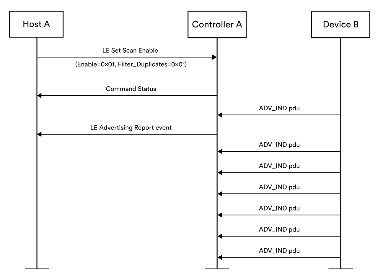 Figure 17 – filtering duplicate advertising PDUs
The Filter_Duplicates option acts upon all advertising packets from all devices and there is no way to apply it to a specific device only whilst leaving all advertising packets from other devices unfiltered.
Applications therefore have a choice. The first option is to receive all advertising reports and maintain a fairly up to date awareness of whether another device is in range but accept that this will generate a lot of HCI traffic and callbacks to application code. The alternative is to suppress the reporting of duplicate advertising reports but immediately lose track of whether the device of interest continues to stay in range or not. Neither of these options is ideal
5.1.5 Bluetooth LE Audio and Acceptor Availability
In the terminology of the Common Audio Profile (CAP), an Acceptor is a device that can accept an audio stream from another device, known as the Initiator. It’s recommended that Initiators do not use the Filter Accept List (see 4.1.2 Filter Policies) since this is often populated with the addresses of devices to which the Initiator has been bonded. Personal audio devices are likely to have been bonded but LE Audio is about more than just personal audio.
For the optimum user experience, when an audio stream needs to be established, this should happen with as little latency as possible. Keeping track of whether or not a candidate Acceptor is in range is therefore desirable. Scanning for an audio device just to check it is still in range, as a precursor to scanning again and then connecting is a waste of time and energy that has a detrimental affect on latency and the user experience.
LE Audio use cases were amongst the key scenarios that informed the design of the Monitoring Advertisers feature.
5.2 About Monitoring Advertisers
5.2.1 Overview
Using the Filter_Duplicates parameters to suppress the reporting of advertising packets that are identical to one which has already been reported to the host, leaves the host unsure whether the advertising device is still in range when the time comes to connect to it. Connecting is usually preceded by expensive, high duty cycle scanning and if the target device is no longer in range, then this activity will have been a complete waste of energy. The Monitoring Advertisers feature solves this problem.
When the Monitoring Advertisers feature is used, the host instructs the controller to keep track of the presence of one or more advertising devices. Rather than overwhelm the host with an advertising report per received advertising packet, Monitoring Advertisements informs the host once when a monitored device goes out of range and once again if it comes back into range. This provides an efficient way for an application to keep track of devices it might want to connect to. It also takes into account the application’s signal strength requirements.
When the application decides to connect to one of the monitored devices, having been notified that the device is in range, the scanning that precedes connecting is unlikely to be a wasted effort. The target device should be present and in range and so scanning will yield an advertising packet to which a connection request can be sent in response.
Monitoring Advertisers operates independently of the Filter Accept List (see 4.1.2 Filter Policies) and therefore makes it easy to use the Filter Accept List for bonded devices only and Monitoring Advertisers for all devices in general, regardless of whether or not they have been bonded with the scanning device.
There are many situations and product types that will benefit from the Monitoring Advertisers feature through improved energy efficiency and a better user experience. LE Audio devices that initiate audio stream (CAP Initiators) are one category of product for which this feature has been defined.
5.2.2 Technical Highlights
5.2.2.1 Monitored Advertisers List
The Bluetooth Core Specification defines the Monitored Advertisers List. This is a data structure in the controller which contains a list of advertising devices that the host wants to keep track of.
Several parameters accompany each device in the list and each entry can be thought of as having an associated timer. In addition, each entry has a state called Awaiting RSSI High which is maintained by the implementation. This state indicates whether the monitored device is in range. If Awaiting RSSI High is true then the device is not in range.
An understanding of the parameters in the Monitored Advertisers List provides an understanding of how monitoring by the controller works.
|
Parameter(s) |
Description |
|---|---|
|
Address and Address Type |
The address and address type of the device to be monitored. These two parameters allow the controller to identify and monitor the device.
|
|
RSSI Threshold Low |
If the RSSI of all advertising packets from this monitored device stays at or below this value for the period of time indicated by the Time Out parameter then it is said that a loss-of-signal has occurred. When this happens, the controller notifies the host using an HCI LE Monitor Advertisers Report event. The state of this device set to Awaiting RSSI High.
|
|
RSSI Threshold High |
If the RSSI of an advertising packet received from this monitored device is greater than or equal to this value, and the device state is Awaiting RSSI High then the controller sends a HCI LE Monitor Advertisers Report event to the host to inform it that the device is in range. The state for this device is cleared or set to indicate that it is no longer awaiting an RSSI above the high threshold and the timer that is used to monitor for loss of signal is reset.
|
|
Time Out |
A time in seconds used to monitor for signal loss. If no RSSI measurement exceeds the RSSI Threshold Low parameter in this period then loss-of-signal is said to have occurred.
|
5.2.2.2 Host Controller Interface
The host configures the Monitoring Advertisers list and receives events relating to monitored devices using the Host Controller Interface (HCI). Three commands are defined and one event.
|
HCI Command or Event |
Description |
|---|---|
|
LE Monitored Advertisers List command |
Used by the host to add or remove an entry from the Monitored Advertisers List or to clear the list completely. An array of one or more devices to be monitored plus their associated RSSI thresholds and timeout parameter are provided in this command.
|
|
LE Monitored Advertisers Enable command |
Allows the host to enable or disable advertiser monitoring in the controller.
|
|
LE Read Monitored Advertisers List Size command |
Allows the host to determine the total number of entries the controller can currently accommodate in its Monitored Advertisers list. Note that this value may change at any time.
|
|
LE Monitored Advertisers Report event |
Generated by the controller whenever for a monitored device there is a loss-of-signal or the device comes back into range. The Condition parameter indicates which of these two conditions is responsible for the event having been generated.
|
5.2.2.3 Example
Figure 18 provides an illustration of Monitoring Advertisers in action. The left-hand half of the illustration contains a message sequence chart. An advertising device is depicted as a whole entity whilst a scanning device is divided into its controller and host parts so that the HCI communication between the two parts can be seen.
The right-hand half of the diagram shows RSSI values, the low and high RSSI thresholds that have been set, and timer and Awaiting RSSI High state information.
Time flows from the top to the bottom of the diagram. Points of interest are labeled alphabetically on the left-hand timeline. Table 8 summarizes.
|
Point |
|
|---|---|
|
A |
The scanner’s host starts by asking the controller how many advertising devices it can monitor. The host then adds a device to the list along with RSSI low, RSSI high and timeout values (not shown). Finally, the host tells the controller to enable advertiser monitoring. |
|
B |
At this point the illustration starts to show advertising packets transmitted by the first device. Note that the device could have been advertising prior to this point but the packets are only shown from here. Received packets have an RSSI that is greater than the configured low threshold and so the timer for the monitored device is reset as each packet is received. |
|
C |
The next few packets received after point C have an RSSI that is lower than the low RSSI threshold and so it is at point C that the timer is last reset and the timer runs from that point. |
|
D |
A series of low RSSI packets are now received and at point D, a timeout occurs. The controller indicates the loss of signal condition to the host by sending a LE Monitor Advertisers Report event with condition == 0x00. The device is now in the Awaiting High RSSI state in the monitoring advertisers list. |
|
E |
At point E, the first of a series of packets whose RSSI is above the low threshold is received. For each such packet, the timer is reset. |
|
F |
At point F, the RSSI value exceeds the RSSI High threshold. The host is informed that the monitored device is back in range with a sufficiently strong signal via a LE Monitor Advertisers Report event with condition == 0x01 sent by the controller. The device is no longer in the Awaiting High RSSI state. |
Table 8 – Monitoring Advertisers Example – Points of Interest
 Figure 18 – An example of Monitoring Advertisers in use
6. ISOAL Enhancement
6.1 Background
This section explains aspects of Bluetooth LE technology that are relevant to the enhancements made to the Isochronous Adaptation Layer (ISOAL) of the Bluetooth LE stack.
6.1.1 Isochronous Communication
The Bluetooth LE data transport architecture includes the LE CIS and LE BIS logical transports, where CIS stands for Connected Isochronous Stream and BIS is Broadcast Isochronous Stream. These logical transports are supported by the LE Isochronous Physical Link and the LE Isochronous Physical Channel.
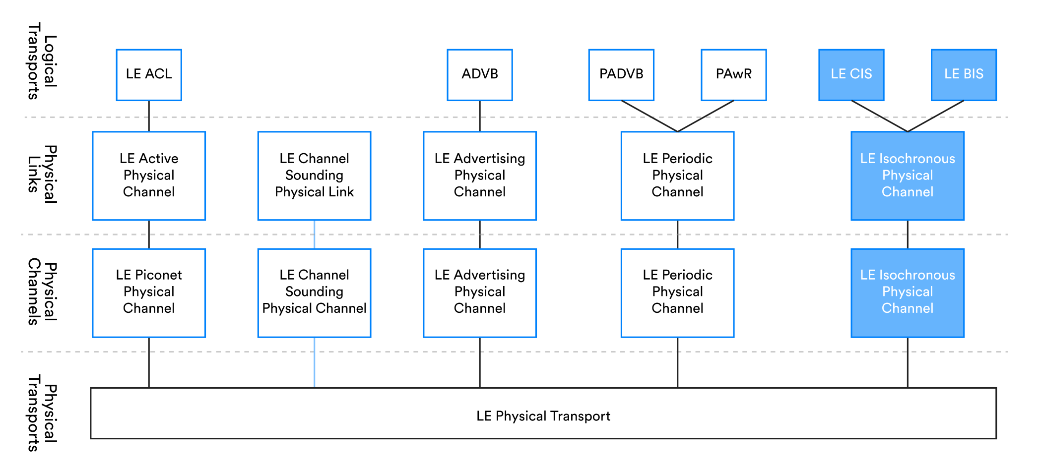 Figure 19 – Isochronous communication and the data transport architecture
Isochronous communication is used when the data to be transferred between devices is time-bound. This means that there is a strict relationship with time that must be adhered to when receiver(s) process the transmitted data.
Bluetooth LE Audio uses isochronous communication, and this ensures that multiple streams of related data will be rendered by their respective receivers at the same time. To put this in more concrete terms, it means for example, that audio data for the left stereo channel and audio for the right stereo channel can be transmitted at different times by the audio source device but will be rendered by two, separate audio sink devices (e.g. left and right earbuds) for the two stereo channels, at the same time and in the manner expected by the user.
CIS provides a connection-oriented approach to isochronous communication. CIS generally involves small groups of devices such as a smartphone and a pair of hearing aids, for example. Communication can be bidirectional though, so a hearing aid could include a microphone and act both as an audio source as well as an audio sink.
BIS involves the broadcasting of isochronous data and is intended for the delivery of isochronous data such as audio to a large group of devices. Communication is unidirectional, however.
Isochronous communication, particularly when handling audio data involves a number of challenges.
The first is the correct synchronization of the rendering of data (in this case the playback of audio) across multiple, completely independent devices. This is precisely the issue that isochronous communication is designed to address.
Latency is sometimes an issue and at other times it is not. The user is only likely to be aware of latency if they have some other reference against which to compare the expected timing of sounds in their audio devices and the actual timing of sounds that they experience. For example, if a hearing aid user can hear some ambient sounds as well as the same sounds transmitted to their hearing aids then if there is significant latency, the user will perceive a lag between the ambient sounds and their amplified counterparts. Bluetooth isochronous communication allows the selection of low latency configurations to help meet the requirements of such devices.
Reliability is important because there is limited tolerance for data loss in many audio scenarios. Both CIS and BIS include mechanisms that enhance reliability.
6.1.2 Digital Audio
Isochronous communication is not solely for audio applications but it is the key use for which it was originally designed. The way in which digital audio data is produced creates certain challenges and a layer in the Bluetooth LE stack called the Isochronous Adaptation Layer (ISOAL) addresses them.
Audio is transformed into a digital format through a process known as sampling. Sampling involves measuring and recording the amplitude of a signal at regular intervals and this produces a significant amount of data which in the context of Bluetooth LE Audio is data that will ultimately need to be transmitted.
Bluetooth LE Audio uses a codec called LC3[4] which applies a compression algorithm to the sample data and significantly reduces its size. Codecs generally work by recognizing and exploiting patterns found in a series of consecutive samples. So for a codec to work, it needs a whole series of samples to analyze at a time.
A collection of samples analyzed at one time by a codec is known as a frame. Frames have a fixed duration, normally measured in milliseconds and contain a number of samples determined by the sample rate. For example, a 10ms frame contains 441 samples if the sample rate is 44.1 KHz.
6.1.3 ISOAL
6.1.3.1 ISOAL in the Bluetooth Architecture
Data such as digital audio is produced by the application layer of a system. This resides in the host part of the Bluetooth stack and is commonly either an operating system (OS) service or a user application running on the OS. In the Bluetooth Core Specification, the layer that provides data for isochronous communication is simply called the upper layer.
The Bluetooth link layer communicates data to one or more other devices using one of the isochronous logical transports. The link layer is implemented in the Bluetooth controller which is usually a system on a chip.
ISOAL exchanges isochronous data in Service Data Units (SDUs) with ISOAL and ISOAL exchanges Protocol Data Units (PDUs) with the link layer. Figure 20 shows the relationship between these three parts of a Bluetooth system.
 Figure 20 – ISOAL in the Bluetooth architecture
The host and controller are typically, discreet, independent components and communicate with each other using the Host Controller Interface over one of the supported transports such as USB or UART.
6.1.3.2 Issues addressed by ISOAL
There are two important areas where differences between the operational parameters of the data producer in the upper layer and those governing the link layer may cause complications.
The first concerns the size of the SDUs produced in the upper layer. It is common for the SDUs to be significantly larger than the maximum size PDU that is supported by the link layer.
ISOAL makes it possible for the upper layer to produce larger SDUs than the link layer can handle in a single PDU.
The second issue concerns timing. The transmission of data by the link layer takes place in events which occur at intervals. This interval can take a range of values and is referred to generally as the ISO Interval. Frames are produced by the upper layer at intervals too and are passed down the stack in SDUs where SDU stands for Service Data Unit. The time interval time governing SDU production by the upper layer is called the SDU Interval.
The ISO Interval which is used by the link layer in the controller is often not the same as the SDU Interval used by the upper layer in the host and the two interval values are not integer multiples of each other. In addition, it is common for there to be no synchronization between the activities of these two layers and as a result there can be delays spent waiting as data passes through system. It should be noted that if the link layer doesn’t have data from the upper layer to transmit during an event, a null PDU is transmitted.
Figure 21 shows the impact of SDU and PDU production being unsynchronized.
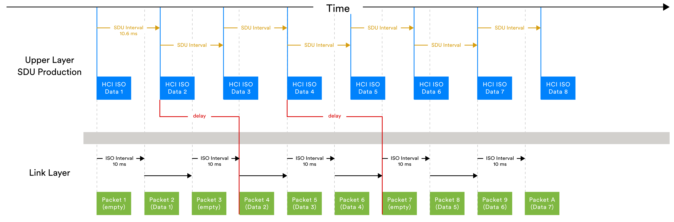 Figure 21 – unsynchronized SDU and PDU production
The data to be transmitted is strongly bound to time and receivers must be able to restore that time relationship and ensure that when the data is processed, the expected result is achieved. This is always an issue but it is more complicated when there is no synchronization between the upper layer and the transport.
ISOAL allows the rate of production of SDUs by the upper layer to differ from the rate of transmission of isochronous PDUs by the link layer and for their operation to be unsynchronized.
6.1.3.3 ISOAL processing paths
There are two possible paths for the isochronous data to take through ISOAL and these are depicted with different colors in Figure 22.
If the SDU Interval is an integer multiple of the ISO Interval and the operation of the upper layer and transport layer are synchronized, then unframed PDUs are produced via a process called fragmentation. Otherwise, framed PDUs are produced and a process called segmentation is applied.
 Figure 22- ISOAL
6.1.3.4 Unframed and Framed PDUs
If the unframed PDU path is used then SDUs that are larger than the maximum PDU size that the link layer allows are split into smaller parts by a process called fragmentation. Headers indicate whether a fragment is the whole SDU, the start, the continuation or the end of an SDU.
In the reverse direction, SDUs are recombined from the smaller unframed PDUs received from the link layer.
If the framed PDU path is used then a process called segmentation is applied to SDUs. Like fragmentation, this splits SDUs into smaller parts with headers but the header that indicates the start of an SDU also contains timing offset information so that the receiver can reassemble and retain this critical timing information.
SDUs are transmitted in one or more link layer PDUs, depending on the outcome of the fragmentation or segmentation process.
6.1.3.5 Framing Mode
A framing mode is defined in the Bluetooth Core Specification. Prior to version 6.0, only two framing modes were defined, each corresponding to the framed or unframed case.
6.1.3.6 Issues with ISOAL Segmentation
The ISOAL framing process deals with two aspects of the data passed to it from the upper layer. It makes it possible to transmit larger SDUs by segmenting them into smaller PDUs and it ensures that the relationship the data has with time is retained and can be reconstructed.
There are two problems with segmentation that may or may not be significant, depending on the application.
The first concerns reliability. In any wireless communications system, there is always some probability of packet loss. If an SDU containing say, audio data is split into multiple PDUs for transmission over the air in a corresponding series of link layer packets then the probability of any one or more of these packets being lost and therefore the SDU as a whole being compromised is increased.
The second concerns latency. If segmentation is applied then the upper layer on the receiving device must wait until it has received all segments of the SDU before it can reassemble and process it. In the case of audio, this means recreating an audio frame and decoding it using the LC3[5] codec before moving on to the audio rendering stage. This wait time translates into latency.
6.2 About the ISOAL Enhancement
The Isochronous Adaptation layer has a new framing mode called Unsegmented Framed mode. Hosts may select this mode by specifying a value of 0x02 in the Framing parameter of the HCI LE Set CIG Parameters command or the LE Create BIG command.
The unsegmented framing mode allows framed PDUs to be used and the timing information of each SDU retained but without requiring the application of segmentation. This new framing mode has two benefits. Firstly, latency due to the segmentation process is eliminated. Secondly, the risk of SDU loss due to packet loss is reduced.
6.2.1 Reduced Latency
By eliminating segmentation from the framing process, each link layer packet effectively contains a whole SDU. This corresponds to a whole audio frame in the case of LE Audio and the upper layer does not need to wait for a series of packets to be received before it is in a position to decode and process the received audio data.
6.2.2 Improved Reliability
When segmentation is applied, a single SDU is transported as the payload of multiple packets. Assuming a constant probability of packet loss, the more packets are required to transport an SDU in its entirety, the greater the probability that one or more parts of the SDU will be lost.
When the unsegmented framing mode is used, the maximum PDU size is always sufficient to contain a whole SDU without the need for segmentation. There is therefore a one-to-one relationship between SDUs from the upper layer and the PDUs that the link layer transmits. Consequently, the risk of packet loss does not increase in the way that it does when segmentation produces multiple PDUs for each SDU.
7. LL Extended Feature Set
7.1 Background
The link layer (LL) is a complex layer of the Bluetooth LE stack. Numerous capabilities, known as features are defined.
Support for a feature is often optional. Before using a feature or engaging in a LL procedure which relates to or depends upon one of these features, a device needs to establish whether or not the feature is supported by both its own Bluetooth controller and the controller of the remote device. To that end, the Bluetooth Core Specification defined an 8-octet bit mask called FeatureSet and a feature exchange procedure.
The definition of FeatureSet assigns meaning to each of its 64 bits. A bit value of 1 means the associated feature is supported and a value of 0 means that it is not.
The Feature Exchange Link Layer Control procedure involves the exchange of LL_FEATURE_REQ and LL_FEATURE_RSP PDUs when initiated by the Central device in a connection. The Peripheral may initiate the procedure too but does so by sending a LL_PERIPHERAL_FEATURE_REQ PDU to which the Central replies with LL_FEATURE_RSP. All three of these PDU types contain the FeatureSet bit mask that indicates the features supported by the transmitting device. Figure 23 shows the Feature Exchange link layer control procedure when initiated by the Central device, depicted here as device A.
 Figure 23 – Central-initiated LL Feature Exchange Procedure
Over time, Bluetooth has become increasingly sophisticated and its list of features has grown. The 64 bits of the FeatureSet bit mask are no longer sufficient to cover the large range of features as defined by Bluetooth Core Specification version 6.0 and future versions of that document.
Figure 24 shows the end of the table that defines the meaning of bits in the FeatureSet field as at version 5.4 of the Bluetooth Core Specification. Only bit number 63 is unassigned here.
 Figure 24 – The FeatureSet field as at version {Atlanta version number} of the Bluetooth Core Specification
7.2 About LL Extended Feature Set
7.2.1 Overview
LL Extended Feature Set provides a means by which further features beyond those for which a bit has been assigned within the FeatureSet field can be indicated as supported or not supported by devices. It has been designed to support the evolution of Bluetooth technology well into the future, with sufficient capacity to accommodate 1984 support indication bits.
7.2.2 Technical Highlights
LL Extended Feature Set is itself a link layer feature which a device either supports or it does not. This is indicated by the value of bit number 63 in the FeatureSet field.
The FeatureSet bitmask has been enlarged and is divided into addressable pages. Page 0 contains the first 64 bits and these are defined as per the field’s specification prior to version 6.0 of the Bluetooth Core Specification. There then follow 10 pages numbered sequentially starting from 1 and each 192 bits (24 octets) in size.
Devices which support the LL Extended Feature Set feature may discover each others extended feature set using the Feature Page Exchange procedure. The procedure may be initiated by either the Central device or the Peripheral device.
Two new HCI commands and a new HCI event have been defined for use with the LL Extended Feature Set. These are the LE Read All Local Supported Features command, the LE Read All Remote Features command and the LE Read All Remote Features Complete event respectively.
A call to the LE Read All Remote Features command results in the transmission of a series of LL_FEATURE_EXT_REQ PDUs, each of which is responded to by the remote device with a LL_FEATURE_EXT_RSP PDU. When all remote FeatureSet pages have been retrieved the details are reported to the initiating host in a LE Read All Remote Features Complete event. See Figure 25.
 Figure 25 – LL Extended Feature Set Exchange
Both the LL_FEATURE_EXT_REQ and LL_FEATURE_EXT_RSP PDUs have the same structure, with three fields in the link layer data PDU CtrData field. Table 9 shows the fields in these PDU types.
|
CtrData |
||
|---|---|---|
|
MaxPage (1 octet) |
PageNumber (1 octet) |
FeaturePage (24 octets) |
Table 9 – Content of the LL_FEATURE_EXT_REQ and LL_FEATURE_EXT_RSP PDUs
The MaxPage field is used to indicate the highest numbered page in which there is a non-zero bit.
The PageNumber field identifies the number of the 24-octet page within the extended FeatureSet whose values are being requested or reported.
FeaturePage contains the 192 bit values contained within the page identified by PageNumber.
The Feature Page Exchange procedure may be started by the Host or autonomously by the link layer. New versions of existing HCI commands and events have been defined to enable use of the extended feature set feature by Hosts.
8. Frame Space Update
8.1 Background
This section explains aspects of Bluetooth LE technology that are relevant to the Frame Space Update enhancement.
8.1.1 The Inter Frame Space
The link layer defines an air interface protocol, and this includes the definition of a time interval called the Inter Frame Space (IFS).
The IFS must be included between two consecutive packets sent on the same channel. Prior to Bluetooth Core Specification version 6.0, this time period was referred to using the symbolic identifier T_IFS and had a fixed value of 150 µs.
Minimum time durations that must exist between the end of the last packet transmitted in an event or subevent and the start of the next event/subevent are also defined for the various transport types.
8.1.2 The Connected State
Figure 9 depicts the link layer state machine. Two logical transport types can operate in the connection state. These are the asynchronous connection-oriented logical transport (ACL) and the connected isochronous stream (CIS).
The ACL transport allows one device acting in the Central role to exchange packets during connection events with another single device acting in the Peripheral role.
Figure 26 shows an example ACL connection as defined prior to version 6.0 of the Bluetooth Core Specification, with the fixed value T_IFS defining the time gap that must exist between packets in the same connection event sent either from Central to Peripheral or from Peripheral to Central. In addition, there must be a period of at least T_IFS between the end of one connection event and the start of the next.
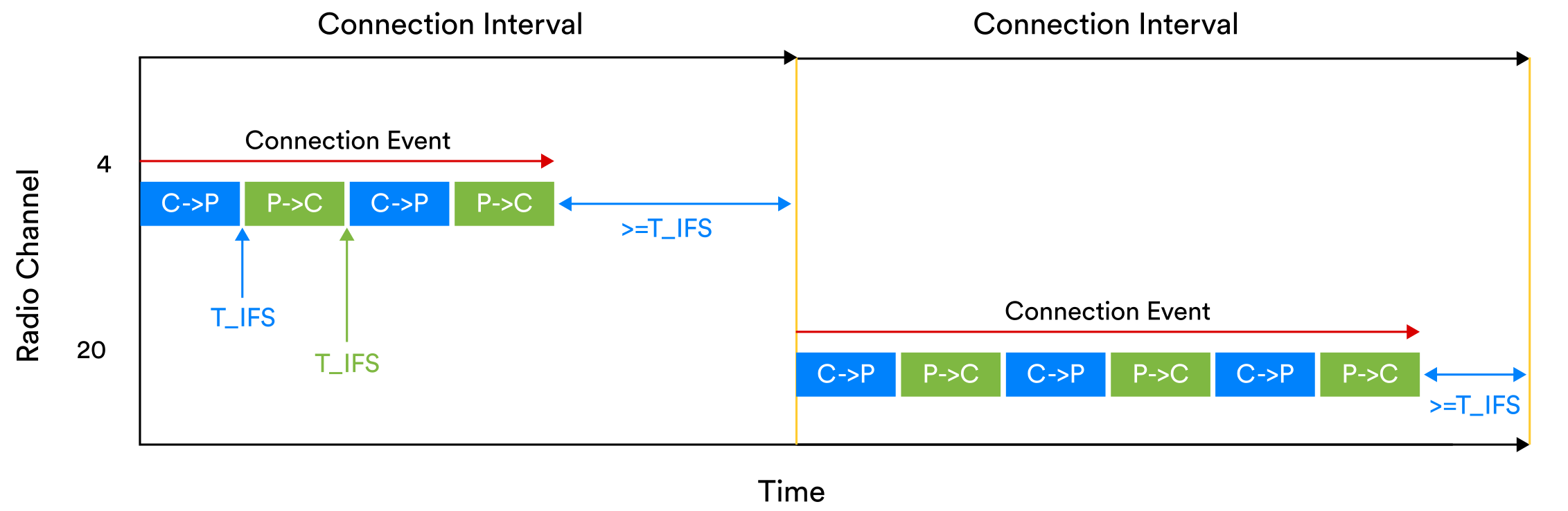 Figure 26 -Packets exchanged over an ACL connection
CIS uses a system of subevents during which packets are exchanged. The timing gap between packets in the same subevent prior to version 6.0 was also defined as the fixed value T_IFS as shown in Figure 27. In addition, a time period called the Minimum Subevent Space which has the symbolic name T_MSS is defined. There must be a period of at least T_MSS between the end of one CIS subevent and the start of the next. In the Bluetooth Core Specification before version 6.0, T_MSS had the same fixed 150 µs value as T_IFS. It should be noted that a CIS has an associated ACL connection which is used to establish the CIS and to exchange link layer control PDUs that affect the CIS.
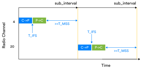 Figure 27 – packets exchanged over a connected isochronous stream (CIS)
8.2 About Frame Space Update
8.2.1 Overview
Bluetooth Core Specification version 6.0 makes the following changes to frame spacing:
- Five distinct symbolic names have been allocated for the time spacings that apply to ACL connections and CIS.
- Values are no longer fixed at 150 µs.
- Values for each of the five frame spacing types default to 150 µs but new values may be negotiated by the Central and Peripheral devices after a connection has been established.
Frame space values may be either shorter or longer than the default 150 µs.
The change is only relevant to ACL connections and connected isochronous streams. Other transport types continue to use a fixed inter frame spacing of 150 µs which is now referred to with the symbolic name T_IFS_150.
Shorter frame space values can increase overall throughput. Examples of applications that will benefit from a shorter frame space and higher data throughput rates include:
- Fitness trackers which have to transfer all accrued data in one go to a connected device such as a smartphone or laptop.
- Firmware updates.
- Bluetooth LE Audio. Audio packets sent over a connected isochronous stream can be sent more quickly, in shorter bursts. This reduces the probability of collisions from other devices from occurring.
- Devices that use their radio for other purposes such as Wi-Fi have more time for these activities.
Longer frame space values may benefit controllers which have relatively low processing power, allowing more time for the controller to process longer packets.
8.2.2 Technical Highlights
8.2.2.1 Spacing Types
Three spacing types are defined for ACL connections. Table 10 summarizes the new spacing types for ACL connections.
|
Spacing Type Symbolic Identifier |
Definition |
|---|---|
|
T_IFS_ACL_CP |
The duration of the required spacing time which must exist from the end of a packet transmission by the Central device and the start of the following slot in the same connection event, which may potentially be used by the Peripheral.
|
|
T_IFS_ACL_PC |
The duration of the required spacing time from the end of a packet transmission by the Peripheral device in a connection and the start of the following slot to potentially be used by the Central in the same connection event.
|
|
T_IFS_END |
The minimum time to elapse between the end of a connection event and the start of the next one.
|
Table 10 – New Frame Spacing Types and Identifiers for ACL connections
Figure 28 depicts connection events and packet transmission in an ACL connection with the new spacing types indicated by their symbolic identifiers.
 Figure 28 – new frame spacing types in an ACL connection
Two spacing types are defined for connected isochronous streams. Table 11 summarizes the new spacing types for CIS.
|
Spacing Type Symbolic Identifier |
Definition |
|---|---|
|
T_IFS_CIS |
The duration of the required spacing time from the end of a packet transmission by the Central device in a CIS and the start of the following transmission by the Peripheral.
|
|
T_MSS_CIS |
The minimum subevent space which is the minimum time that must elapse between the end of a packet transmitted in one subevent and the start of the next subevent.
|
Table 11 – new Frame Spacing Types and Identifiers for CIS
Figure 29 depicts subevents and packet transmission in a connected isochronous stream with the new spacing types indicated by their symbolic identifiers.
 Figure 29 – new frame spacing types in a connected isochronous stream (CIS)
Controllers may be configured to use distinct values for each of the spacing types per Bluetooth LE PHY (LE 1M, LE 2M and LE Coded).
In all cases the default value for a spacing parameter is 150 µs and the permitted range of values that a spacing parameter may be set to is 0 to 10,000 µs.
In all cases, a tolerance of ±2 µs is allowed.
8.2.2.2 Frame Space Update
The link layer specification defines a new procedure called the Frame Space Update procedure. It is by using this procedure that devices may negotiate values for each applicable spacing types for some or all supported PHYs.
Either the Central device or the Peripheral device may initiate the Frame Space Update procedure. This is accomplished by sending a LL_FRAME_SPACE_REQ over the connection. In response, the other device must send a LL_FRAME_SPACE_RSP PDU.
The LL_FRAME_SPACE_REQ PDU includes the following fields:
|
Field |
Meaning |
|---|---|
|
FS_MIN |
The minimum requested frame spacing in microseconds. |
|
FS_MAX |
The maximum requested frame spacing in microseconds. |
|
PHYs |
A single octet bit mask where bit 0 indicates the LE 1M PHY, bit 1 indicates the LE 2M PHY and bit 2 indicates the LE Coded PHY. One or more of these bits may be set to indicate the PHYs for which the frame spacing update is being requested.
|
|
Spacing Type |
A 2-octet bit mask which indicates the spacing parameters for which new values are being requested. Bit 0 indicates T_IFS_ACL_CP, bit 1 indicates T_IFS_ACL_PC, bit 2 indicates T_IFS_END, bit 3 indicates T_IFS_CIS and bit 4 indicates T_MSS_CIS.
|
The responding device validates the request, applying rules from the Bluetooth Core Specification. If the request is valid and can be accommodated then it returns a LL_FRAME_SPACE_RSP PDU containing the frame space value to be used. This will be the lowest value from within the requested range that the device can support. Both devices adopt the new values and notify their Hosts of the change.
If the request cannot be accommodated, it returns a LL_REJECT_EXT_IND PDU with the error code set to Unsupported Feature or Parameter Value and the frame spacing parameters in use are unchanged.
8.2.2.3 Host Controller Interface
The Host Controller Interface has been updated to support the new Frame Space Update procedure.
The procedure is initiated by a Host sending the new HCI_LE_Frame_Space_Update command to its controller. The command contains the spacing types and range of times within which new frame space values are requested, and the PHYs to which new values should apply.
Changes are notified to the Host on completion of the Frame Space Update procedure via the new LE Frame Space Update Complete event.
Figure 30 shows the interactions that take place between host and controller and between devices when the frame space update procedure is initiated.
 Figure 30 – Frame Space Update HCI and Link Layer interactions
9. Conclusion
Bluetooth Core Specification version 6.0 continues the trend for Bluetooth technology to be regularly updated with new features and technical improvements.
Channel Sounding will enable a standards-based, secure approach to reliable and accurate distance measurement and many types of products will benefit.
Decision-Based Advertising Filtering will improve throughput and reliability when using Bluetooth extended advertising for connectionless data transfer.
Monitoring Advertisers will be useful to application developers and enable the provision of better user interfaces and an improved user experience.
The improvements made to ISOAL will benefit those audio applications for which low latency as perceived by the user, is important.
The LL Extended Feature Set capability enables feature support discovery in the most sophisticated, feature-rich devices of today and into the future.
10. References
| Item | Location |
|---|---|
|
Bluetooth Core Specification version 6.0 |
|
|
The Bluetooth LE Security Study Guide |
https://www.bluetooth.com/bluetooth-resources/le-security-study-guide/ |
|
Bluetooth® Channel Sounding Technical Overview paper |
FOOTNOTES
[1] Mode-0 will be explained in 3.2.2.5.1 Events, Subevents and Steps
[2] Gaussian Frequency Shift Key
[3] Connectable advertising PDUs are ones which allow a connection request to be made as a response
[4] Low Complexity Communications Codec
[5] Low Complexity Communications Codec – the audio codec used by Bluetooth LE Audio